Driving device for wool spinning machine

A transmission device and spinning frame technology, which is applied to spinning machines, continuous winding spinning machines, textiles and papermaking, etc. It can solve the problems that cannot meet the requirements of fine spinning technology, it takes a lot of time to change gears, and the range of transmission speed is different. Large and other problems, to achieve the effect of convenient design of model changes, reduction of machining costs and assembly workload, and reduction of overall machine power

Active Publication Date: 2012-10-03
常州市同和纺织机械制造有限公司
View PDF10 Cites 10 Cited by
  • Summary
  • Abstract
  • Description
  • Claims
  • Application Information

AI Technical Summary

Problems solved by technology

However, the above-mentioned transmission device often needs to design a variable speed gearbox, and the transmission speed range of each road varies greatly. The synchronous speed of the main motor is 1500m/min, and the speed of the spindle is required to be 12000~20000r/min. It is 0.5~5r/min, which is very slow and needs to be decelerated by 300~3000 times. The mechanical deceleration can only be achieved through 7~9 stages of deceleration. The structure is complex, takes up a lot of space, and requires more gear trai...

Method used


Image

  • Driving device for wool spinning machine

Examples


Embodiment Construction

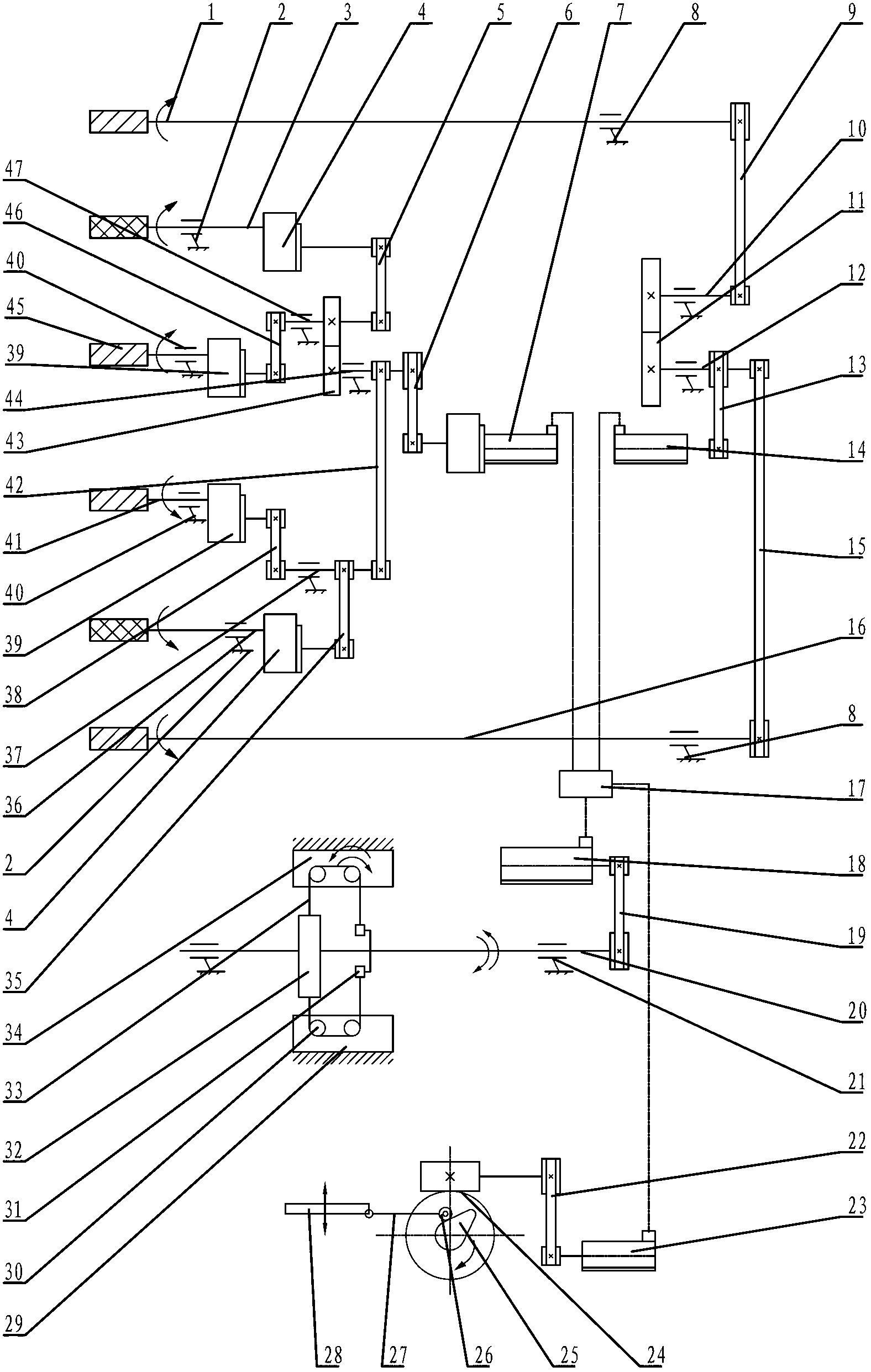
[0019] See figure 1 As shown, the transmission device of the wool spinning frame of the present invention includes a drafting transmission mechanism composed of a front roller transmission mechanism and a middle rear roller transmission mechanism, as well as a spindle transmission mechanism and a lifting transmission mechanism.

[0020] See figure 1 As shown, the front roller transmission mechanism of the present invention includes front roller motor 14, left front roller 1 and right front roller 16 installed on the front roller seat 8 respectively, and front roller motor 14 decelerates all the way through first belt drive 15 and right front roller 16 or The left front roller 1 is connected, and the other road is connected with the left front roller 1 or the right front roller 16 through the first bridge gear transmission pair 11 and the second belt drive 9, and the front roller motor 14 is connected with the first speed reduction belt drive 13, and the first speed reduction b...


PUM


Abstract

The invention relates to a driving device for a wool spinning machine. After a front roller motor decelerates, one path of front roller motor subjected to deceleration is connected with a front-right roller through the driving of a first belt; the other path of front roller motor subjected to deceleration is connected with a front-left roller through driving of a first intermediate gear pair and a second belt; after a rear-middle roller motor decelerates, one path of rear-middle roller motor subjected to deceleration is connected with an intermediate roller gearbox through driving of a third belt and a fourth belt; the other path of rear-middle roller motor subjected to deceleration is connected with the intermediate roller gearbox through driving of a second intermediate gear pair and a fifth belt; left and right intermediate rollers are connected with the intermediate roller gearbox; the third belt drives to be connected with a rear roller gearbox through the driving of a sixth belt; the second intermediate gear pair is connected with a rear roller gearbox through driving of a seventh belt; left and right rear rollers are connected with the rear roller gearbox; after a main motor decelerates, the main motor subjected to deceleration is connected with a spindle through a spindle belt via a main shaft and a rolling disk; and a lifting motor subjected to deceleration is connected with a ring rail through a worm gear and worm transmission pair, a stroke cam, a cam roller and a swing rod. The driving device disclosed by the invention has the advantages of simple structure, reduced amount of driving mechanisms and reduction of production cost.

Description

technical field [0001] The invention relates to a transmission device of a wool spinning frame and belongs to the technical field of wool spinning frames. Background technique [0002] The mechanical transmission device of the traditional wool spinning frame is generally realized by the suction motor, the ring plate lifting motor and the main motor. The main function of the suction motor is to generate negative pressure in the bellows and air duct to solve the function of spinning interrupted end suction or accumulation. The function of the ring plate lifting motor is to complete the function of the ring plate descending at the beginning of spinning or full bobbin doffing during the spinning process. The main motor is the key to the transmission of the wool spinning frame. The main motor drive is called the main drive. The main drive part includes main functions such as spindle drive, draft drive, twist drive, and lifting drive. The spindle drive, draft drive, twist The tr...

Claims


Application Information

Patent Timeline
IPC IPC(8): D01H1/20D01H1/22D01H1/24
Inventor 陈祖英邵向涛周源杨德钱王洁
Owner 常州市同和纺织机械制造有限公司
Why Eureka
Try Eureka