
Guide drilling tool for developing shale gas

A technology for directional drilling and shale gas, applied in directional drilling and other directions, can solve the problems of small plunger pump design space, low precision of drilling tools, slow piston response, etc., and achieve smooth wellbore trajectory, which is conducive to miniaturization and response fast effect

Active Publication Date: 2012-10-03
INST OF SINOPEC OILFIELD EQUIP CORP +1
View PDF6 Cites 11 Cited by
  • Summary
  • Abstract
  • Description
  • Claims
  • Application Information

AI Technical Summary

Problems solved by technology

The other is the dynamic push against type rotary drilling method, the guide push arm is obviously damaged due to pushing against the well wall
In addition, foreign commercial directional drilling tools are mostly equipped with turbine power generation systems. Baker Hughes’ AutoTrak RCLS uses turbine power generation to power the measurement and control system and hydraulic system, and Schlumberger’s PowerDrive SRD uses turbine power generation to power the stable platform; The radial plunger pump is used in the drilling tool, and the radial plunger pump is driven by the rotation between the rotating central shaft and the guide sleeve. Due to the action of the radial plunger pump, the guide sleeve will rotate, causing the guide The guiding precision of the drilling tool is reduced, and the radial plunger pump is adopted at the same time. Due to the limitation of the radial size of the guide sleeve, the design space of the plunger pump is very small, resulting in a small displacement of the pump and slow response of the piston when it is working.

Method used


Image

  • Guide drilling tool for developing shale gas
  • Guide drilling tool for developing shale gas
  • Guide drilling tool for developing shale gas

Examples


Embodiment Construction

[0020] Embodiments of the present invention will be further described below in conjunction with the accompanying drawings.

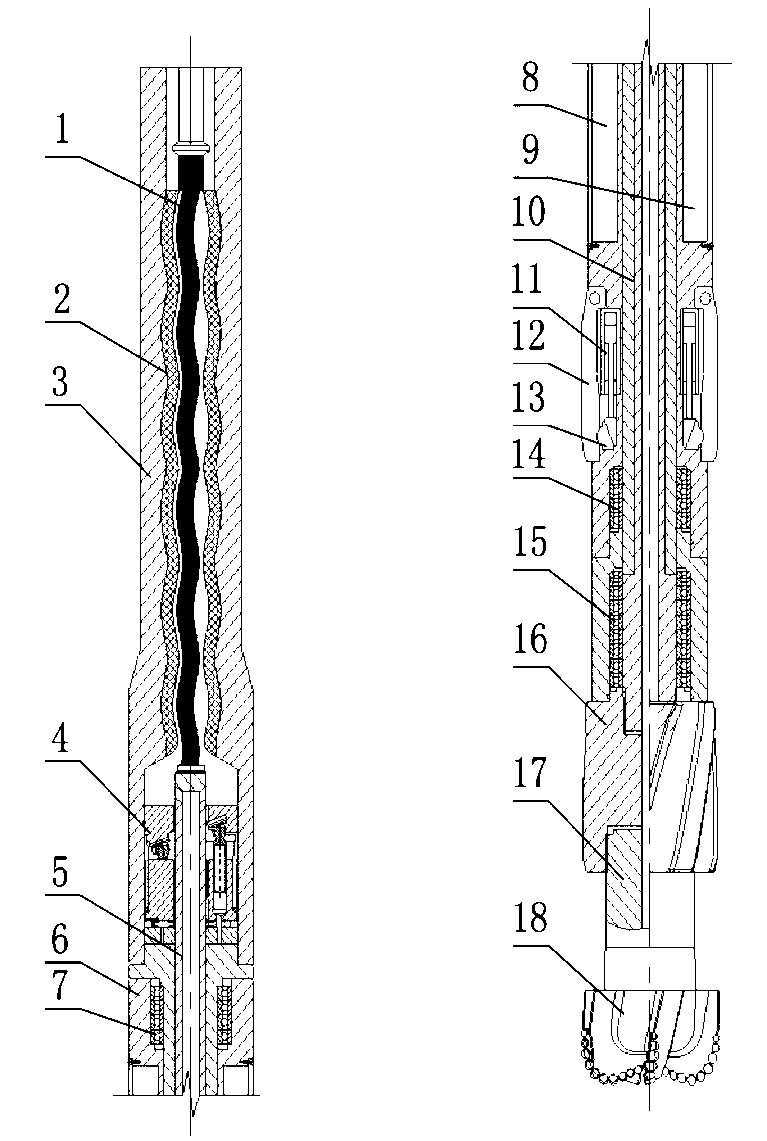
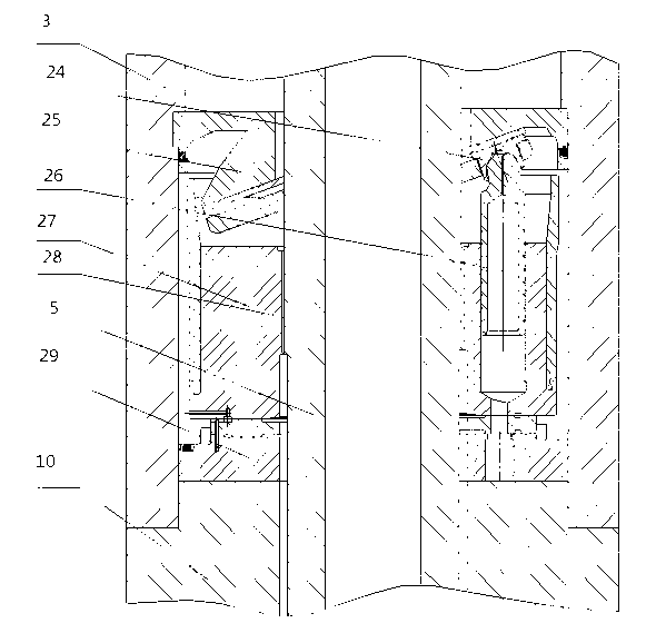
[0021] like figure 1 As shown, a steerable drilling tool for shale gas development includes a screw drilling tool 1, a rubber bushing 2, a flexible cardan shaft 5, a transmission shaft 10, a guide sleeve 6 and a casing 3 set outside the screw drilling tool, and the screw The upper end of the drilling tool is connected with the drill collar, the lower end is connected with the flexible universal joint shaft 5, the flexible universal joint shaft 5 is connected with the transmission shaft 10, the lower end of the transmission shaft is connected with the drill bit 18 through the stabilizer 16, and the stabilizer 16 is connected with the drill bit 18 through the short joint 17. The drill bit 18 is connected, the transmission shaft 10 and the guide sleeve 6 are connected by the upper bearing 7 and the lower bearing 14 to form a relatively rotatable structure, ...


PUM


Abstract

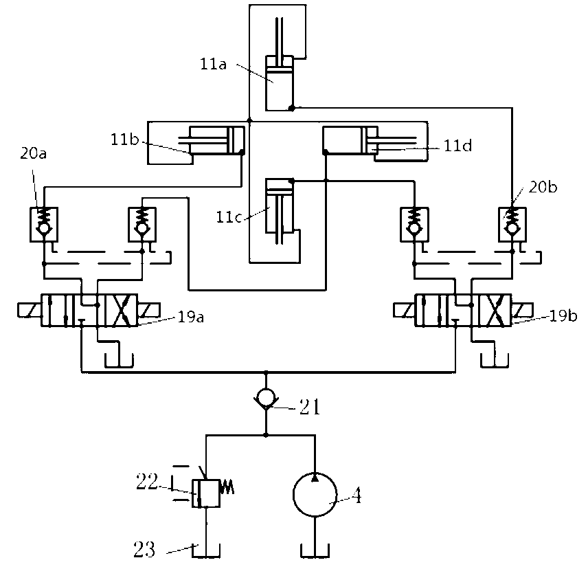
The invention discloses a guide drilling tool for developing shale gas. The guide drilling tool comprises a spiral drilling rig, a transmission shaft, a hydraulic system, a guide sleeve and a shell sleeved outside the spiral drilling rig, wherein the periphery of the lower end of the guide sleeve is provided with four oil cylinders which are parallel to the axial direction and are uniformly distributed on the guide sleeve at the included angles of 90 degrees; every two oil cylinders which are 180 degrees away from each other form a pair of reverse synchronous oil cylinders, so that two pairs of reverse synchronous oil cylinders are formed; four guide push arms are arranged on the guide sleeve corresponding to the four oil cylinders; one end of each guide push arm is hinged on the guide sleeve; and the piston rod ends of the four oil cylinders are arranged together with the other end of the guide push arm through a push block respectively, so that an adjustable upper stabilizer is constructed. The guide push arm is equivalent to a controllable eccentric upper stabilizer, and is combined with a lower stabilizer which rotates near a drill bit, so that a well track is smoother, and the control accuracy and efficiency of the well track are increased.

Description

technical field [0001] The invention relates to a steering drilling tool, in particular to a steering drilling tool for shale gas development. Background technique [0002] Shale gas as an unconventional energy source. In the development of unconventional energy shale gas, in order to increase gas production, it is usually necessary to drill horizontal wells, but due to the anisotropy of the formation, the wellbore trajectory often deviates, which brings certain difficulties to the development of shale gas. [0003] At present, the traditional horizontal well development technology is divided into three-stage drilling of vertical well section, augmented well section and horizontal well section, which takes a lot of time and virtually increases the development cost. However, foreign advanced directional drilling tools can be used in the whole well section in the development of horizontal wells, which can reduce the number of trips and greatly improve the operating efficiency...

Claims


Application Information

Patent Timeline
Patent Type & Authority Applications(China)
IPC IPC(8): E21B7/04
Inventor 张策胡鹏吴刚
Owner INST OF SINOPEC OILFIELD EQUIP CORP
Learn More