Optimal design method for inducer with varying pitch of centrifugal pump

An optimized design and technology of centrifugal pumps, applied to components, pumps, pump components, etc. of pumping devices used for elastic fluids, can solve problems such as increased unstable forces, decreased efficiency of inducers, and decreased hydraulic efficiency of pump main impellers , to achieve the effect of improving efficiency, enhancing operation stability and improving performance

Active Publication Date: 2012-10-03
JIANGSU UNIV
View PDF3 Cites 7 Cited by
  • Summary
  • Abstract
  • Description
  • Claims
  • Application Information

AI Technical Summary

Problems solved by technology

However, there are still some deficiencies in the existing variable-pitch inducer design method: (1) The outlet diameter of the inducer determined by the existing calculation method is larger than that of the pump inlet. If the diameter of the inducer outlet is reduced, the head of the inducer will be reduced , and affect its efficiency, if the inlet diameter of the main impeller of the pump is increased, the head and efficiency of the main impeller of the pump will be affected, so it is difficult to optimize the cooperation between the inducer and the main impeller of the pump; (2) The head coefficient of the inducer is usually based on experience Although selecting a larger value for the head coefficient of the inducer can increase the head of the inducer, it will actually lead to a decrease in the hydraulic efficiency of the main impeller of the pump. Therefore, it is difficult to accurately select the head coefficient of the inducer, which has affected the The optimized fit of the impeller reduces the efficiency and precision of the design

Method used


Image

  • Optimal design method for inducer with varying pitch of centrifugal pump
  • Optimal design method for inducer with varying pitch of centrifugal pump
  • Optimal design method for inducer with varying pitch of centrifugal pump

Examples


Embodiment Construction

[0047]The present invention will be further described below in conjunction with the accompanying drawings and embodiments.

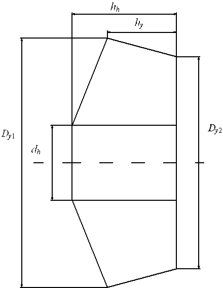
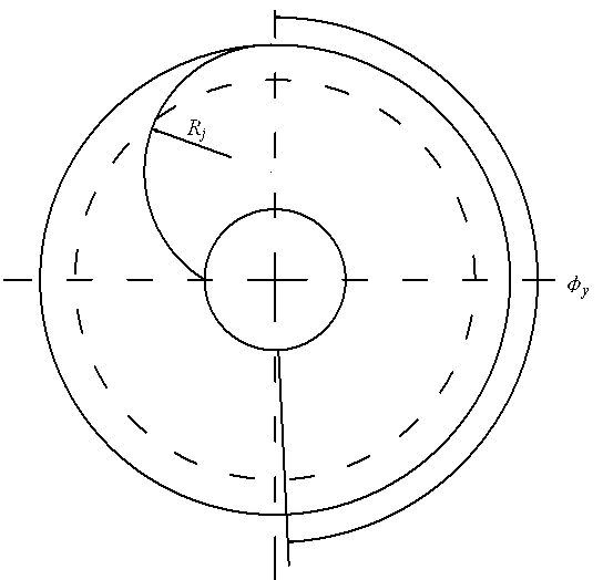
[0048] figure 1 and figure 2 Together determine the shape of this embodiment inducer. It is a cone-tipped inducer.

[0049] (1) Build a test bench for the external characteristics of the centrifugal pump, and the lift of the centrifugal pump H Measured by the pressure gauges at the inlet and outlet of the centrifugal pump; power P Measuring by electrometry; flow Q Read by the electromagnetic flowmeter on the centrifugal pump outlet piping system; efficiency n by the formula n = wxya / P Calculated; the vacuum pump is used to control the vacuum degree of the suction port, so that the centrifugal pump has cavitation, and the necessary NPSH of the centrifugal pump is measured NPSH r ; Calculate the NPSH of the centrifugal pump device according to the measurement of the built test bench NPSH a , NPSH a by the formula Calculated; through...


PUM


Abstract

The invention discloses an optimal design method for an inducer with a varying pitch of a centrifugal pump, belonging to the technical field of pumps. The optimal design method is characterized by comprising the following steps: when designing the inducer with the varying pitch, firstly, determining data such as flow of a peak efficiency point of the central pump, a necessary net positive suction head, a device net positive suction head and the like through experiments, and then determining geometric sizes of diameters of an inlet and an outlet of a rim of the inducer and a rim folding lead according to the experimental data and a flow condition of the inlet of a main impeller of the pump. According to the optimal design method for the inducer with the varying pitch of the centrifugal pump provided by the invention, the inducer and the main impeller of the pump have good energy matching relationship, the performance of the inducer is improved, the operation stability of the system is enhanced, difficulty in selection of a lift coefficient of the inducer according to experience is avoided, and the efficiency for designing the inducer is improved. The optimal design method has a certain popularization value.

Description

technical field [0001] The invention relates to a design method of an inducer of a centrifugal pump, in particular to an optimal design method of a variable-pitch inducer of a centrifugal pump. Background technique [0002] The inducer technology is currently known as one of the most effective ways to improve the cavitation performance of centrifugal pumps and is widely used. The inducer belongs to the axial flow impeller, which is used to improve the cavitation performance of the centrifugal pump, and it can also work in a certain degree of cavitation state. Spiral inducer is a commonly used structure, and can be divided into two forms: equal pitch and variable pitch. Because the blade inlet angle of variable pitch inducer is smaller and the outlet angle is larger, a smaller inlet flow coefficient and a larger lift can be obtained, which better meet the cavitation performance requirements of the inducer itself and the energy at the inlet of the main impeller of the pump. ...

Claims


Application Information

Patent Timeline
IPC IPC(8): F04D29/22F04D29/66
Inventor 刘厚林庄宿国王勇杨东升
Owner JIANGSU UNIV
Why Eureka
Try Eureka