Thick material layer sintering ore sintering distribution control method and distribution device thereof

A control method and a material distribution device technology, applied in the field of metallurgy, can solve problems such as increased edge effects, inability to obtain sintered ore quality, and unsteady sintering flue gas desulfurization rate, and achieve the effects of improving control accuracy and mitigating edge benefits

Inactive Publication Date: 2012-10-03
BAOSHAN IRON & STEEL CO LTD
View PDF4 Cites 10 Cited by
  • Summary
  • Abstract
  • Description
  • Claims
  • Application Information

AI Technical Summary

Problems solved by technology

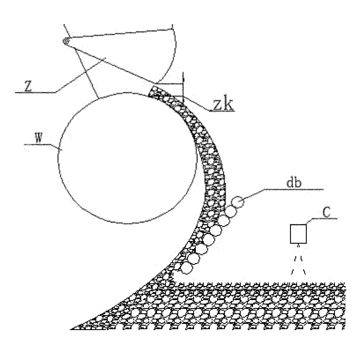
[0009] 1. In the case of thick material layer sintering, the influence of the edge effect of sintering is further increased, and the moving speed of both sides and the middle of the transverse combustion zone is further increased. If the thick material layer is uniform in thickness, it cannot maintain uniform speed and homogeneous combustion. This also limits the precise control of the temperature and position of the sintering end point, and the quality of sintering cannot be further improved.
[0010] 2. After the sintering machine is enlarged, in the process of sintering with thick material layer, the accuracy of the feeding roller to adjust the material layer is limited, and the charging density of the sintering trolley per unit time cannot be finely controlled,

Method used


Image

  • Thick material layer sintering ore sintering distribution control method and distribution device thereof
  • Thick material layer sintering ore sintering distribution control method and distribution device thereof
  • Thick material layer sintering ore sintering distribution control method and distribution device thereof

Examples


Embodiment A

[0098] The first step of embodiment A:

[0099] First of all, when the feeding roller speed is increased from 31.8% to 32.2%, the thickness of the material layer measured by the layer thickness meter at the most end is 750.5mm, and the measured value of the material layer thickness is 750.5mm, which satisfies the condition of (770-750.5)≥10 ; But if the sintering end point temperature does not meet the requirements of 100 ° C ≥ (T measurement - T) ≥ 80, continue to adjust the speed of the feeding roller until it meets the requirements.

[0100] Secondly, when the speed of the feeding roller is increased from 32.2% to 32.8%, the thickness of the material layer measured by the layer thickness meter at the most end is 763mm, and the thickness of the material layer at both ends is maintained at 763mm, which meets the condition of (770-763)≤9 , at this time, the speed of the feeding roller is fixed. The sintering end point temperature is 417.5°C, which meets the requirement of 100...

Embodiment B

[0123] The first step of embodiment B:

[0124] First, when the feeding roller rotates at a speed of 33.1%, the thickness of the material layer measured by the layer thickness meter at the extreme end is 755.5mm, and the measured value of the material layer thickness is 755.5mm, which satisfies the condition of (770-755.5)≥10;

[0125] Secondly, after the feeding roller speed is increased from 33.1% to 33.9%, the thickness of the material layer measured by the layer thickness meter at the most end is 765.5mm, the measured value at the sintering end position at this time is 15.13, and the end point temperature is 422°C, which is consistent with 100°C≥ (422-330) ≥ 80 ℃ requirements, the adjustment of the feeding roller speed is completed.

[0126] For the above calculation results, see the corresponding table of adjustment examples in Table-7.

[0127] Table-7 Adjustment instance correspondence table

[0128]

[0129] The second step of embodiment B:

[0130] pair 2 # 、4 ...

Embodiment C

[0142] The first step of embodiment C:

[0143] First, when the feeding roller speed is 33.1%, the material layer thickness measured by the layer thickness meter at the most end is 755.5mm, which satisfies the condition of (770-755.5)≥10;

[0144] Secondly, after the feeding roller speed is increased from 33.1% to 33.9%, the thickness of the material layer measured by the layer thickness meter at the most end is 765.5mm, which meets the condition of (770-765.5)≤9, and the measured value of the sintering end position at this time is 15.13 , the end point temperature is 422°C, which meets the requirement of 100°C≥(422-330)≥80°C, at this time, the adjustment of the feed roller speed is completed.

[0145] For the above calculation results, see the corresponding table of adjustment examples in Table-10.

[0146] Table-10 Adjustment instance correspondence table

[0147]

[0148] The second step of embodiment C:

[0149] Also, yes 2 # 、4 # The fine-tuning gate is adjusted s...


PUM

PropertyMeasurementUnit
Thicknessaaaaaaaaaa
Thicknessaaaaaaaaaa
Thicknessaaaaaaaaaa

Abstract

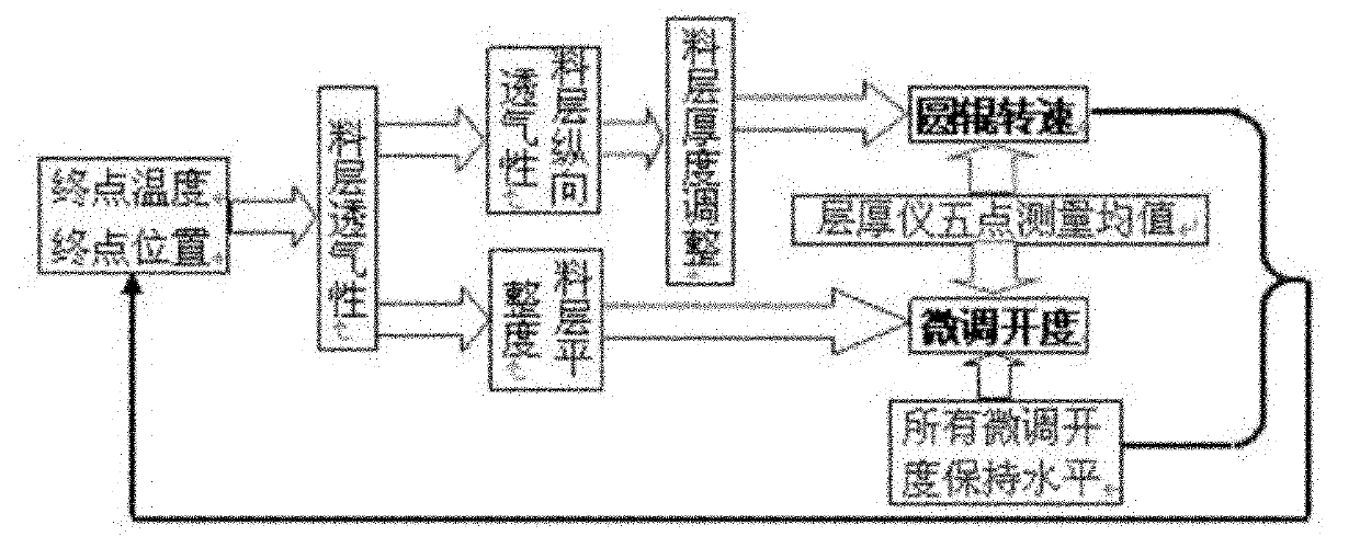
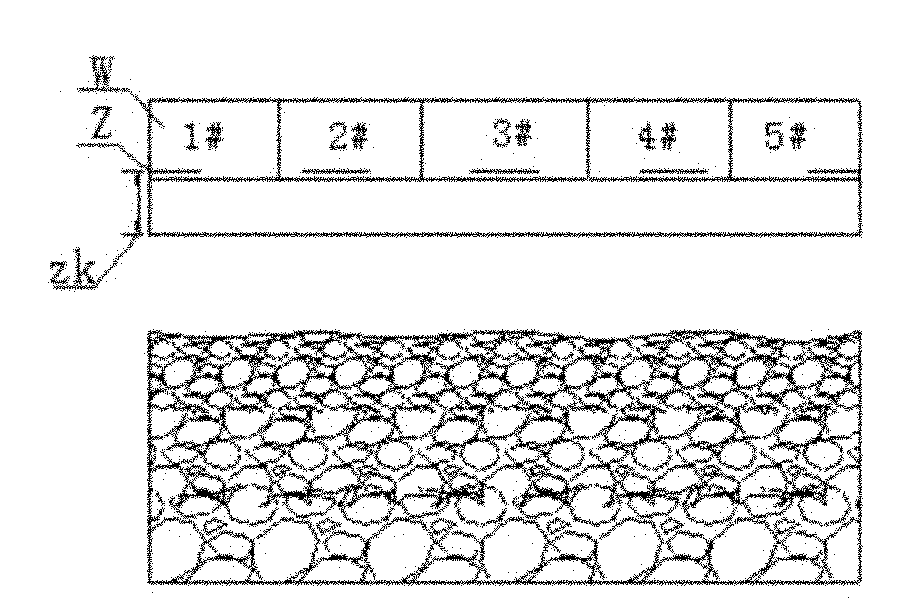
The invention relates to a thick material layer sintering ore sintering distribution control method and a distribution device thereof. 5-7 parts are transversely uniformly distributed on an upper material layer of a bogie; 5-7 fine adjustment gates which correspond to the parts and are transversely arranged along the bogie of a sintering machine are arranged below a main gate, and each fine adjustment gate is used for adjusting a gap between a feeding roll on the corresponding part and the main gate and adjusting the size of feed at the position, so that the thicknesses of the material layers of the corresponding parts on the bogie are controlled. 5-7 layer thickness gauges which correspond to the 5-7 fine adjustment gates are arranged at a sintering end point in front of a multi-roll distributor, change of the thickness of a middle material layer is obtained according to detection results of the layer thickness gauges, the rotation speed of the feeding rolls and/or the opening of the corresponding fine adjustment gates on the different parts are correspondingly adjusted, and concave bevel edges with certain slope are formed on the material layers in the transverse thickness direction of the bogie of the sintering machine after distribution. Accordingly, requirements on a flue gas desulfurization process for large-scale production of the sintering machine are met to the greatest extent while the quality and the yield of sintering ores are stably increased, and annular cooling afterheat recycling heat is improved.

Description

technical field [0001] The invention relates to the field of metallurgy, in particular, the invention relates to a high-precision material distribution control method and a material distribution device for sintering of thick material layer sintering. Background technique [0002] In the ironmaking process, sintering ore is an indispensable process, especially in the production of large-scale blast furnaces, a large amount of sintering ore is required, and the main process of producing sintering ore is to ignite the iron-containing mixture through a sintering machine The air is sintered into blocks. In this production process, in order to improve the output quality of sinter ore and reduce the energy consumption of the process, the average thickness of the material layer feedback control method is adopted in the current known sinter ore production process, that is, by measuring the average value of the transverse layer thickness on the surface of the material layer , to cont...

Claims


Application Information

Patent Timeline
IPC IPC(8): F27B21/14
Inventor 钱文杰何中炜徐明华
Owner BAOSHAN IRON & STEEL CO LTD
Why Eureka
Try Eureka