Device and method for detecting corrosion of metal structure under protective layer through microwave resonance cavity

A microwave resonant cavity and metal structure technology, applied in measurement devices, material analysis using microwave means, instruments, etc., can solve problems such as low resolution, lossy, and easily damaged coating structure, and achieve high resolution and safety. high sex effect

Active Publication Date: 2014-09-03
刘马宝
View PDF3 Cites 2 Cited by
  • Summary
  • Abstract
  • Description
  • Claims
  • Application Information

AI Technical Summary

Problems solved by technology

The visual method is a commonly used intuitive detection method, but its evaluation results cannot accurately reflect the degree of corrosion damage of the metal and is a destructive method
Non-destructive testing methods such as ultrasonic, eddy current and thermal imaging have the disadvantages of complex operation, easy damage to the coating structure, or low resolution. In view of the current non-destructive testing methods for detecting hidden corrosion of metal structures under the protective layer are not perfect, the present invention A method for rapid non-destructive detection of corrosion of metal structures under the protective layer using wave resonator perturbation method is proposed. This method is advanced and has important engineering application value

Method used


Image

  • Device and method for detecting corrosion of metal structure under protective layer through microwave resonance cavity
  • Device and method for detecting corrosion of metal structure under protective layer through microwave resonance cavity

Examples


Embodiment Construction

[0023] The present invention will be described in further detail below in conjunction with the accompanying drawings and specific embodiments.

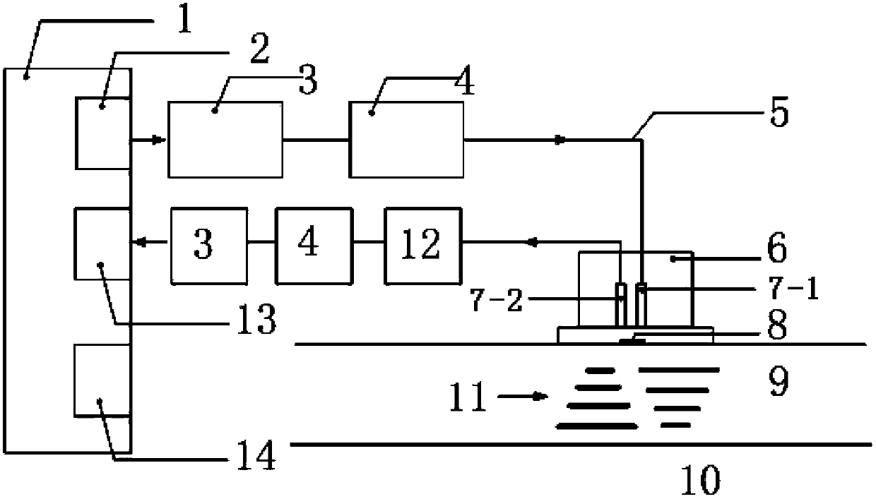
[0024] As shown in the accompanying drawings, a device for microwave resonator detection of metal structure corrosion under the protective layer of the present invention includes an automatic network analyzer 1, a frequency scanning source 2 connected to the automatic network analyzer 1, and the frequency scanning source 2 in turn The connected isolator 3 and adjuster 4, the adjuster 4 is connected with the first coupling probe 7-1 placed in the resonant cavity 6 through the coaxial cable 5, and the second coupling probe 7-1 placed in the resonant cavity 6 The probe 7-2 is connected with the attenuator 12, the adjuster 4, the isolator 3, the signal microprocessor circuit 13) and the automatic network analyzer 1 successively through the coaxial cable 5, and a plurality of corrosion degree indicator lamps 14 are also connected with the a...


PUM

PropertyMeasurementUnit
relative permittivityaaaaaaaaaa
dielectric lossaaaaaaaaaa
relative permittivityaaaaaaaaaa

Abstract

The invention relates to a device and a method for detecting corrosion of a metal structure under a protective layer through a microwave resonance cavity. The device comprises an automatic network analyzer and further comprises a frequency scanning source, an isolator, a distributor and a first coupling probe arranged in a resonance cavity body which are connected with the automatic network analyzer in turn, wherein a second coupling probe arranged in the resonance cavity body is connected with an attenuator, the distributor, the isolator, a signal microprocessor circuit and the automatic network analyzer in turn through a coaxial cable; a plurality of corrosion degree indicator lamps are connected with the automatic network analyzer; and an opening of the resonance cavity body is formed at the lower end of the resonance cavity body. The method comprises the following steps: detecting amplitude-frequency characteristics of the resonance cavity and a detected object at different corrosion degrees, and obtaining resonant frequency, peak power and half-power bandwidth, thereby obtaining the corrosion degree of the metal structure under the protective layer. The device has the advantages of simple structure, high speed and convenience in detection, high reliability, and capability of realizing the detection for the corrosion degrees of the metal structures under the protective layers in different thickness.

Description

technical field [0001] The invention relates to the technical field of metal material corrosion detection, in particular to a device and method for detecting corrosion of a metal structure under a protective layer by a microwave resonator cavity. Background technique [0002] Magnesium alloys, aluminum alloys, and steel parts have the advantages of high specific strength, good plasticity, and easy forming. As important structural materials, they are widely used in various parts of aircraft and other equipment; however, these materials are prone to damage during service. The chemical or physical action of the environmental medium causes gradual deterioration or destruction, and corrosion occurs on the surface of structural parts, such as pitting corrosion, intergranular corrosion and denudation, and stress corrosion. When some key load-bearing components (such as the front beam of the outer wing, the lower wall plate, the small Ji beam, etc.) are severely corroded, the streng...

Claims


Application Information

Patent Timeline
Patent Type & Authority Patents(China)
IPC IPC(8): G01N22/00
Inventor 刘启达尹应增王献辉刘马宝
Owner 刘马宝
Why Eureka
Try Eureka