Supercharge Your Innovation With Domain-Expert AI Agents!

Device for achieving low temperature drift of band-gap reference circuit

A reference circuit, low-temperature drift technology, applied in the direction of adjusting electrical variables, control/regulation systems, instruments, etc., can solve the problems of increased chip area, complex circuits, etc., to achieve low structural power consumption, simple circuit structure, and small layout area Effect

Inactive Publication Date: 2012-10-03
TIANJIN UNIV
View PDF6 Cites 11 Cited by
  • Summary
  • Abstract
  • Description
  • Claims
  • Application Information

AI Technical Summary

Problems solved by technology

However, the above methods will make the circuit more complicated and the chip area will be greatly increased.

Method used


Image

  • Device for achieving low temperature drift of band-gap reference circuit
  • Device for achieving low temperature drift of band-gap reference circuit
  • Device for achieving low temperature drift of band-gap reference circuit

Examples


Embodiment Construction

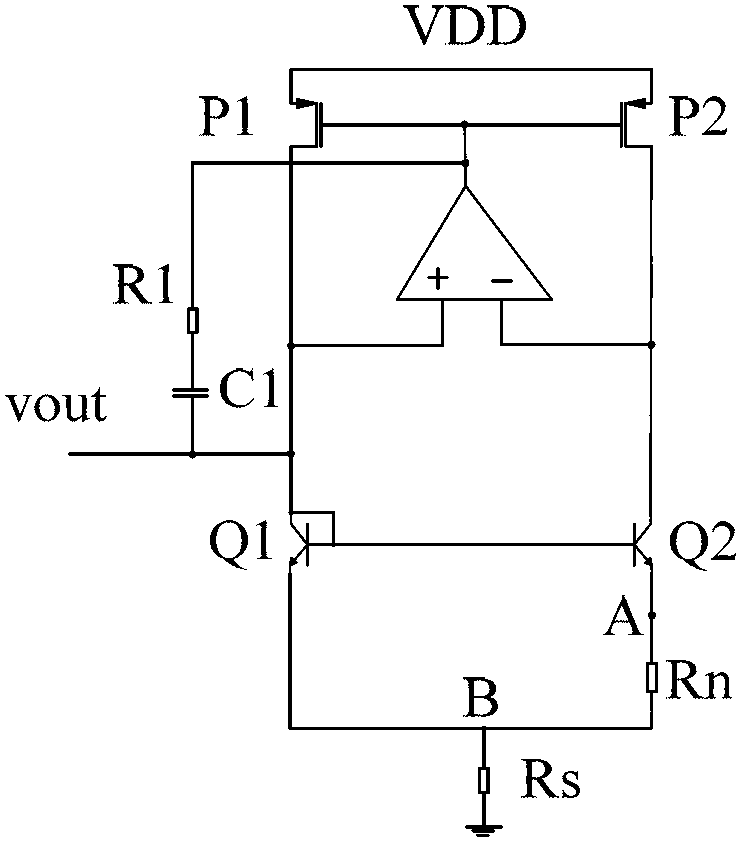
[0027] Will figure 1 The resistor R in S and R n All adopt polysilicon resistance with negative temperature coefficient to realize. The resistance value of this polysilicon resistor varies with temperature as follows:

[0028] R=R o ×[1+T C1 (T-T 0 )+T C2 (T-T 0 ) 2 ] (5)

[0029] where R 0 is the resistance value of the resistor at room temperature, T 0 is room temperature 27°C, T C1 with T C2 are constants, T C1 =-0.003,T C2 = 0.000011. It can be seen from the above formula that when R S / R n When the ratio is constant at room temperature, the ratio will be the same at different temperatures. When the temperature is fixed at a certain value T=T 0 +ΔT, at figure 1 In the structure shown, according to the second item of formula (1), when the temperature is constant, if R S / R n If the ratio is fixed, the voltage at point B will remain constant. At this time, the resistance value deviation caused by the temperature characteristic of the resistance will cau...


PUM


Abstract

The invention relates to the field of an integrated circuit. For using a temperature coefficient of a poly-resistor to compensate a higher order term of negative temperature coefficient voltage, reducing temperature drift of the band-gap reference circuit, the invention uses the technical proposal that the device for achieving the low temperature drift of the band-gap reference circuit comprises MOS (Metal Oxide Semiconductor) tubes P1 and P2, an amplifier, a resistor R1, a capacitor C1, triodes Q1 and Q2, resistors Rs and Rn, wherein the resistors Rs and Rn are polysilicon resistors with negative temperature coefficients; and the variable quantity of the resistance with the temperature is as follows: R=R0*[1+TC1(T-T0)+TC2(T-T0)2] (5), wherein R0 is the resistance under the room temperature, T0 is the room temperature of 27 DEG C, TC1 and TC2 are constants, and T is the current temperature. The device is mainly used for designing and manufacturing a reference voltage generating circuit which is in the band-gap reference circuit and is irrelevant to the temperature.

Description

technical field [0001] The invention relates to the field of integrated circuits, in particular to a design method for a bandgap reference circuit, in particular to a method for realizing low-temperature drift of the bandgap reference circuit by only using the temperature coefficient of resistance. Background technique [0002] The temperature-independent reference voltage generation circuit in the bandgap reference circuit is composed of a diode-generated voltage with a negative temperature coefficient at room temperature and a thermal voltage with a positive temperature coefficient according to a certain proportional relationship. [0003] figure 1 For the structure of the bandgap reference circuit, the Q2 tube is composed of n tubes that are the same as Q1 in parallel, and V BE1 (The difference between the base voltage and the emitter voltage of the transistor Q1) has a negative temperature coefficient, ΔV BE =V T lnn, ΔV BE It is the difference between the base volta...

Claims


Application Information

Patent Timeline
IPC IPC(8): G05F1/567
Inventor 徐江涛于海明高静史再峰姚素英
Owner TIANJIN UNIV
Features
  • R&D
  • Intellectual Property
  • Life Sciences
  • Materials
  • Tech Scout
  • Unparalleled Data Quality
  • Higher Quality Content
  • 60% Fewer Hallucinations
Learn More