blood pump

A blood pump and blood technology, applied in the field of blood pumps, can solve the problems of large pressure gradients of blood pumps, destroy blood cells, etc., and achieve the effect of small space requirements

Inactive Publication Date: 2015-12-16
BERLIN HEART GMBH
View PDF10 Cites 4 Cited by
  • Summary
  • Abstract
  • Description
  • Claims
  • Application Information

AI Technical Summary

Problems solved by technology

[0004] Another difficulty lies in the risk of destroying blood cells (hemolysis), due to the narrowing and abrupt changes in the blood pump (especially at the mechanical bearings of the impellers) in the direction of blood flow through the blood pump, and the large pressure gradients within the blood pump Caused

Method used


Image

  • blood pump
  • blood pump
  • blood pump

Examples


Embodiment Construction

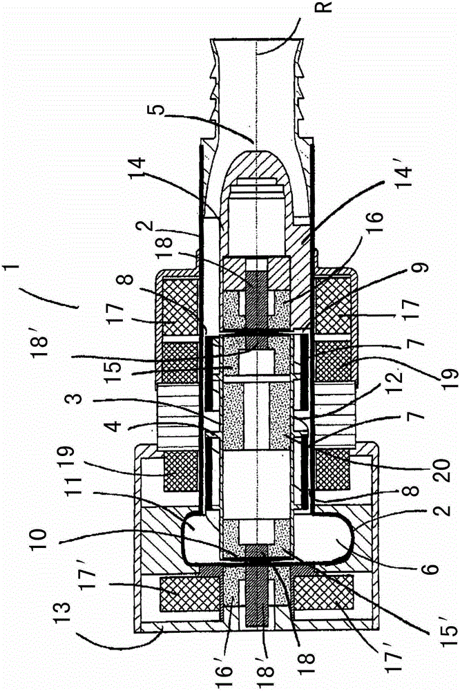
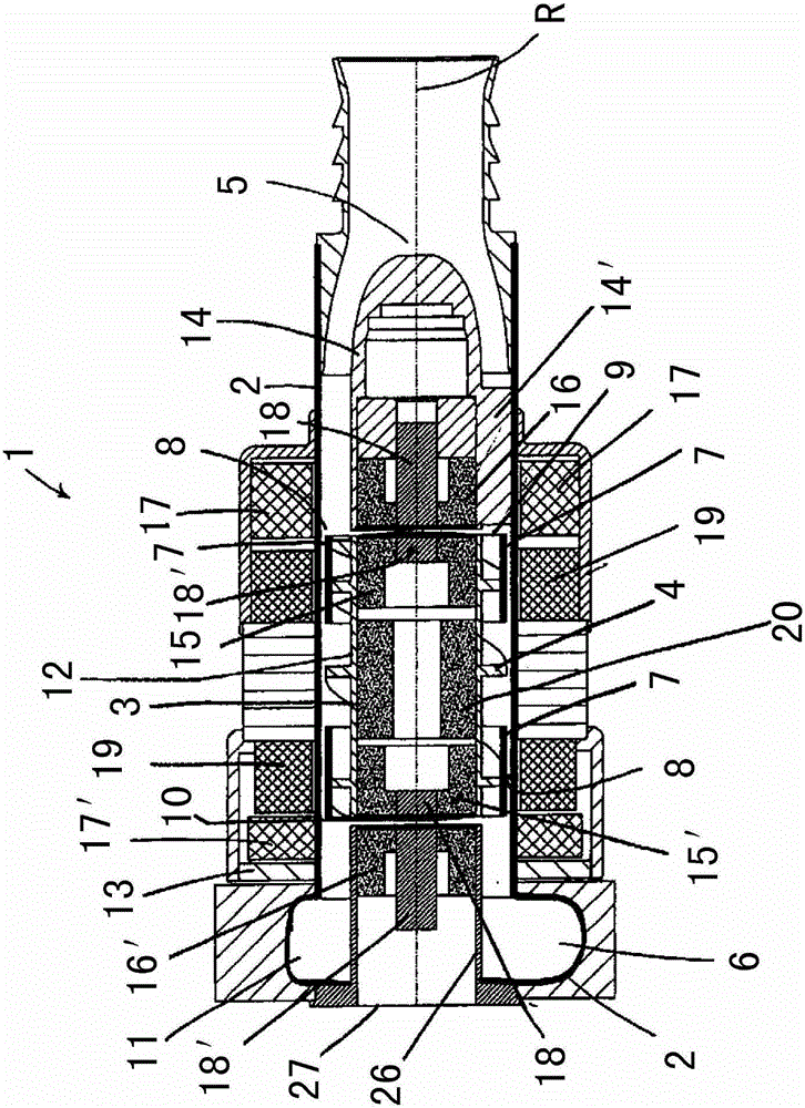
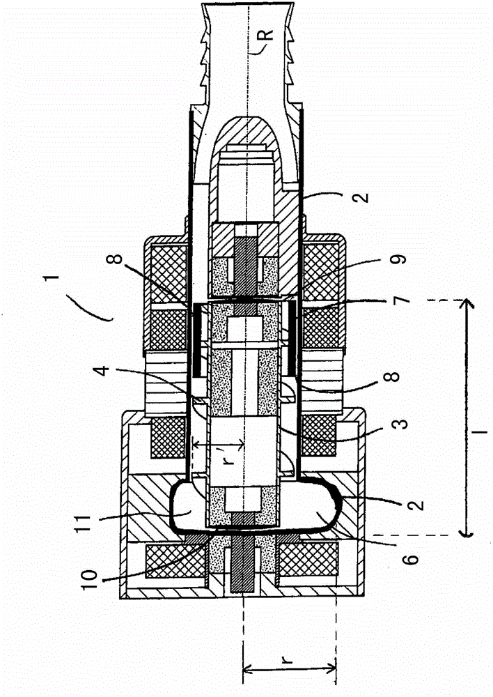
[0058] A schematic diagram of a longitudinal section of a blood pump 1 of the type proposed throughout the text is at Figure 1A shown schematically. The blood pump 1 comprises a hollow body 2 (shown as a thick solid line) in which an impeller 3 with a blade arrangement 4 is arranged. Furthermore, the hollow body 2 comprises an inlet 5 for blood flow in an inflow direction parallel to the axis of rotation R (shown in dashed lines), and an outlet 6 for blood outflow in an outflow direction perpendicular to the section. Thus, in this embodiment example, the outlet is arranged offset at right angles to the axis of rotation R for producing an outflow angle α not equal to zero between the inflow direction and the outflow direction, where α=90°.

[0059] The outlet 6 of the hollow body 2 is arranged between the upstream side 9 of the impeller 3 (the upstream side facing the inlet) and the downstream side 10 of the impeller 3 (the downstream side facing away from the inlet). The inn...


PUM


Abstract

The invention relates to a blood pump (1) comprising a hollow body (2) in which is arranged an impeller (3) with blade means (4) for generating blood along said impeller ( 3) and said blood pump further comprising an at least partially actively stabilized magnetic bearing arrangement (15, 15', 16, 16', 17, 17', 18, 18' for said impeller ) and a hydrodynamic bearing device (7), wherein the impeller (3) can be set to rotate around its axis of rotation (R) by means of a motor stator (19) positioned outside the hollow body, and the hollow body ( 2) comprising an inlet (5) for allowing blood to flow into the hollow body (2) in an inflow direction (E) substantially parallel to the axis of rotation (R), and an outlet (6), the outlet For making blood flow out of the hollow body (2) along the outflow direction (A), the outlet (6) is set to be offset from the rotation axis (R) of the impeller (3), for An outflow angle (α) results between the inflow direction (E) and the outflow direction (A), which angle is not equal to zero, and the blading ( 4 ) is designed as a spiral. The invention also relates to a total artificial heart comprising two blood pumps of the type proposed herein.

Description

technical field [0001] The invention relates to the field of blood pumps. Background technique [0002] A blood pump here and in the following is to be understood as a pump for supporting or generating a blood flow in the human or animal body and is suitable for implantation in the chest cavity of the human or animal and outside the heart. With a left ventricular assist device (LVAD), there is a connection between the left half of the heart and the inlet of the blood pump, and between the outlet of the blood pump and the aorta leaving the heart, to support or generate circulation of blood through the body (systemic circulation) . With a right ventricular assist device (RVAD), there is a connection between the right hemi-heart and the pulmonary trunk leading to the left and right pulmonary arteries (or there is a direct connection between the RVAD and the left and / or right pulmonary artery) to support or Creates circulation of blood through the lungs (pulmonary circulation)...

Claims


Application Information

Patent Timeline
Patent Type & Authority Patents(China)
IPC IPC(8): A61M1/10A61M60/196A61M60/237A61M60/422A61M60/538A61M60/806A61M60/812A61M60/822A61M60/824
CPCA61M2205/04A61M2205/33A61M60/824A61M60/148A61M60/237A61M60/812A61M60/538A61M60/806A61M60/822A61M60/196A61M60/422A61M60/419
Inventor H-E·彼得斯约尔格·穆勒K·杰拉琛P·努瑟尔M·高勒内尔A·阿恩特
Owner BERLIN HEART GMBH
Why Eureka
Try Eureka