Device for condensation liquefaction recovery of organic exhaust gas

A recovery device and organic waste gas technology, applied in the direction of steam condensation, chemical instruments and methods, separation methods, etc., can solve the problems of secondary water pollution, lower reuse value, high replacement cost, etc., to reduce the cost of waste gas recovery and reuse The effect of high value and simple structure

Active Publication Date: 2012-10-10
GUANGDONG PHNIX ECO ENERGY SOLUTION
View PDF6 Cites 7 Cited by
  • Summary
  • Abstract
  • Description
  • Claims
  • Application Information

AI Technical Summary

Problems solved by technology

[0002] Chinese patent 200810026356.7 discloses a process and device for recovering organic waste gas. This patent involves a technology for the adsorption of organic gases by porous materials mainly based on activated carbon. This technology has the following defects in application; 1. Activated carbon materials are used in After repeated use, the adsorption performance gradually decreases, and it needs to be replaced to a certain extent, and the replacement cost is very high
2. After the adsorption of activated carbon is saturated, it needs to be desorbed with steam, which will cause secondary water pollution. Moreover, the organic solvent desorbed by steam has a high water content, and the reuse value is reduced.

Method used


Image

  • Device for condensation liquefaction recovery of organic exhaust gas
  • Device for condensation liquefaction recovery of organic exhaust gas

Examples


Embodiment 1

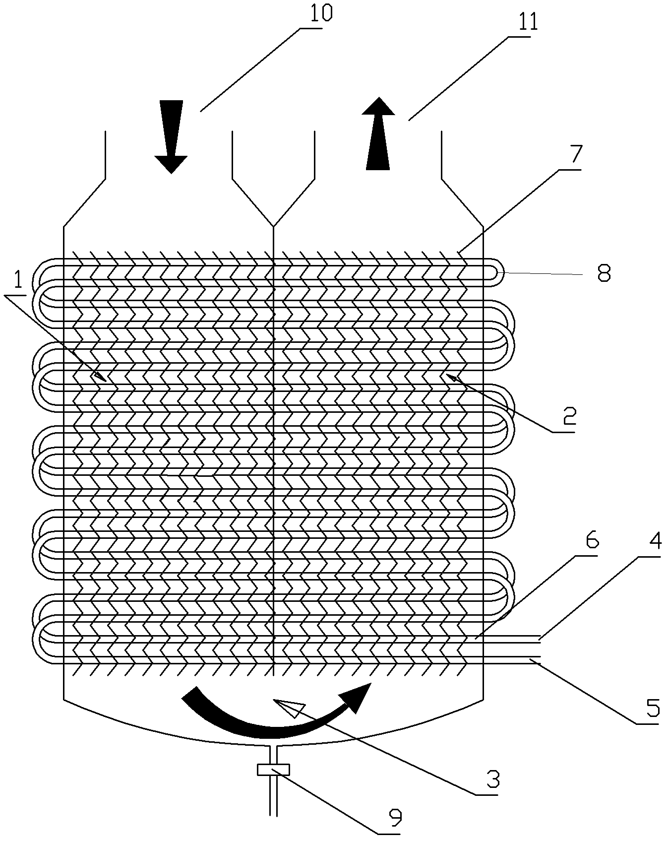
[0021] Embodiment 1: as figure 1 As shown, the organic waste gas condensate liquefaction recovery device includes an inlet heat exchange chamber 1, an outlet heat exchange chamber 2, and a liquid inlet pipe 6, and heat sinks 7 are respectively arranged in the inlet heat exchange chamber 1 and the outlet heat exchange chamber 2, and the inlet The liquid pipe 6 detours upwards from low to high and then turns back close to the original path. The horizontal pipe sections of the liquid inlet pipe 6 pass through the heat sinks 7 respectively; The top of the chamber 2 is provided with an outlet 11; the bottom of the air inlet heat exchange chamber 1 communicates with the bottom of the air outlet heat exchange chamber 2 through a sealed connection chamber 3, and the sealed connection chamber 3 is provided with a discharge control outlet. Its sealed connection cavity is funnel-shaped. The discharge control outlet is connected to the discharge valve 9. The sealed connection chamber ca...

Embodiment 2

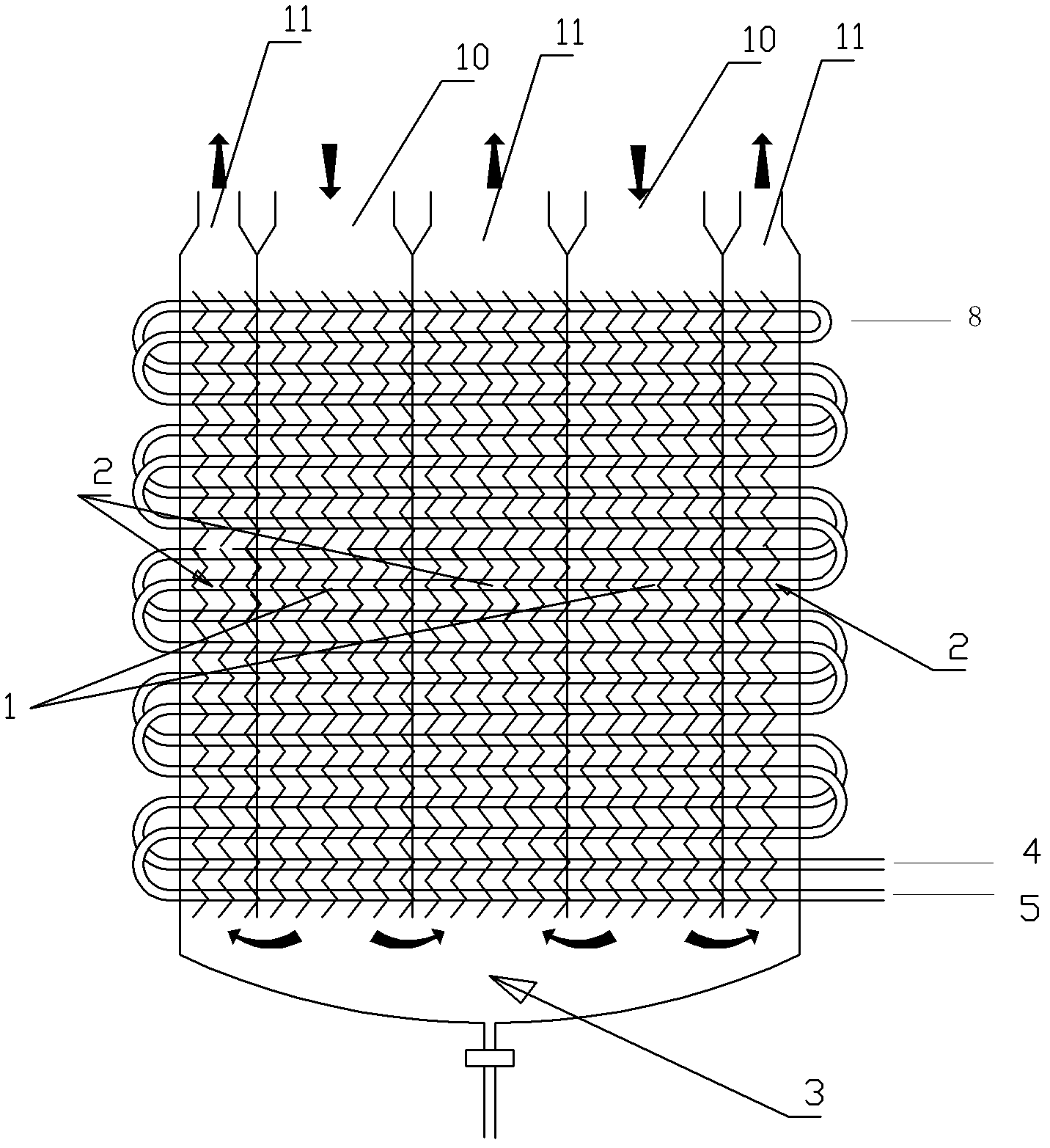
[0051] Embodiment 2: as figure 2 As shown, the organic waste gas condensate liquefaction recovery device is characterized in that it includes an inlet heat exchange chamber, an outlet heat exchange chamber, and a liquid inlet pipe. The heat exchange chamber and the air outlet heat exchange chamber are arranged in sequence, the intake heat exchange chamber is located between two adjacent air outlet heat exchange chambers, or the outlet heat exchange chamber is located between two adjacent intake heat exchange chambers; The heat exchange chamber and the air outlet heat exchange chamber are respectively equipped with cooling fins. The liquid inlet pipe extends from low to high and then turns back close to the original path. The horizontal pipe sections of the liquid inlet pipe pass through the heat sinks respectively; The top of the chamber is provided with an inlet, and the top of the outlet heat exchange chamber is provided with an outlet; the bottom of the inlet heat exchange...

Embodiment 3

[0054] Embodiment 3: The sealed connection chamber is provided with a liquid storage chamber, and the liquid storage chamber is located at the lowest position of the device. In this way, no matter whether the device is placed horizontally or inclined, as long as the liquid storage cavity is kept at the lowest position of the device, it can have a liquid storage function. All the other are with embodiment 1.


PUM


Abstract

The invention discloses a device for condensation liquefaction recovery of organic exhaust gas. The device is characterized in that the device comprises an inlet gas heat exchange chamber, an outlet gas heat exchange chamber and a liquid inlet pipe; cooling fins are respectively arranged in the inlet gas heat exchange chamber and the outlet gas heat exchange chamber; the liquid inlet pipe circuitously extends upward from bottom to top and then goes back to the initial position along a route close to an original route; all horizontally-arranged horizontal pipe sections of the liquid inlet pipe respectively pass through the cooling fins; the top of the inlet gas heat exchange chamber is provided with an inlet; the top of the outlet gas heat exchange chamber is provided with an outlet; the bottom of the inlet gas heat exchange chamber is communicated with the bottom of the outlet gas heat exchange chamber by a sealing connection chamber; and the sealing connection chamber is provided with an outlet. The device for condensation liquefaction recovery of organic exhaust gas is environmentally friendly, has high efficiency, saves energy, reduces a cost of exhaust gas recovery, has a simple structure, and has functions of recovering organic exhaust gas and dehumidifying air.

Description

technical field [0001] The invention relates to an organic waste gas condensation liquefaction recovery device, in particular to a device for recovering organic solvent and gas waste heat in high-temperature organic waste gas. Background technique [0002] Chinese patent 200810026356.7 discloses a process and device for recovering organic waste gas. This patent relates to a technology for the adsorption of organic gases by porous materials mainly based on activated carbon. This technology has the following defects in application; 1. Activated carbon materials are used in After repeated use, the adsorption performance gradually decreases, and it needs to be replaced to a certain extent, and the replacement cost is very high. 2. After the adsorption of activated carbon is saturated, it needs to be desorbed with steam, which will cause secondary water pollution. Moreover, the organic solvent desorbed by steam has a high water content, and the reuse value is reduced. Contents ...

Claims


Application Information

Patent Timeline
Patent Type & Authority Applications(China)
IPC IPC(8): B01D5/00
Inventor 李贤锡
Owner GUANGDONG PHNIX ECO ENERGY SOLUTION
Why Eureka
Try Eureka