Catalytic conversion method of petroleum hydrocarbon

A catalytic conversion method and petroleum hydrocarbon technology, applied in the field of catalytic conversion of integrated processes, can solve problems such as low sulfur content, reduced processing efficiency, and reduced use efficiency of S-Zorb devices

Active Publication Date: 2012-10-10
CHINA PETROLEUM & CHEM CORP +1
View PDF9 Cites 6 Cited by
  • Summary
  • Abstract
  • Description
  • Claims
  • Application Information

AI Technical Summary

Problems solved by technology

When the regenerative flue gas treatment unit handles lower levels of SO X When flue gas is used, its treatment efficiency will be reduced
In addition, even though hydrogenated wax oil catalytic cracking produces gasoline with low sulfur content, it is still difficult to reduce the sulfur content in gasoline to below 10 μg/g, and gasoline still

Method used


Image

  • Catalytic conversion method of petroleum hydrocarbon
  • Catalytic conversion method of petroleum hydrocarbon

Examples


Embodiment 1

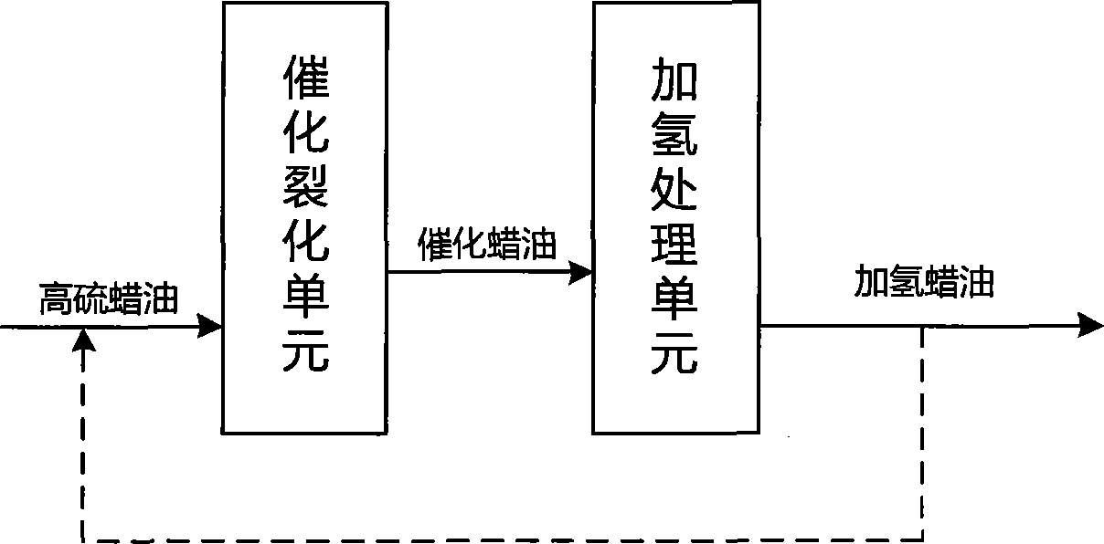
[0059] This example illustrates the product distribution and product properties of raw material A after being treated by a medium-sized catalytic cracking unit and a medium-sized hydrotreating unit using the method provided by the present invention.

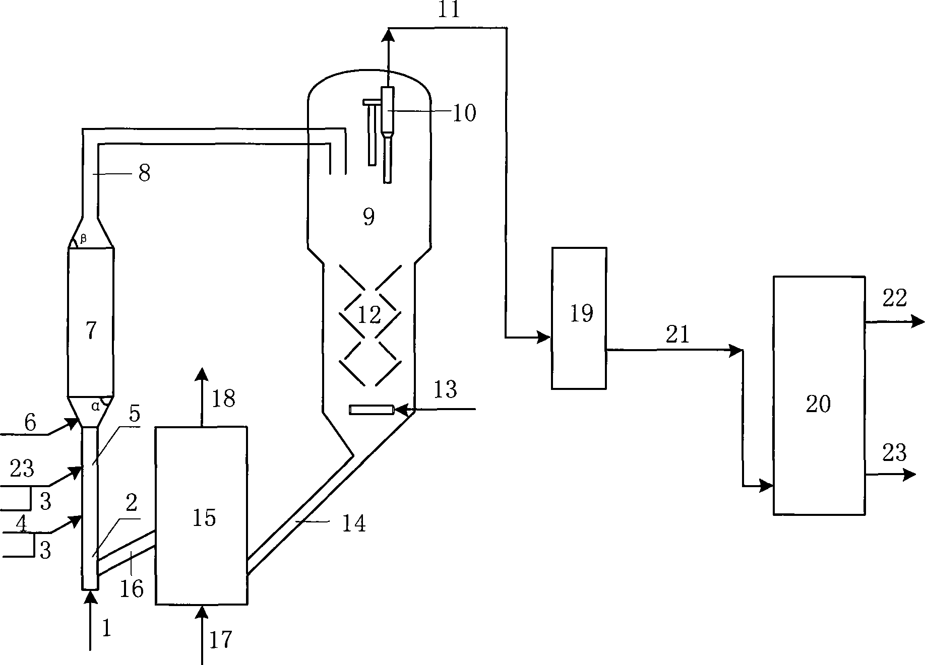
[0060] The preheated raw material A is first processed in a medium-sized catalytic cracking unit. The total height of the pre-lifting section, the first reaction zone, the second reaction zone, and the outlet zone of the reactor of the medium-sized catalytic cracking unit is 15 meters, and the diameter of the pre-lifting section is 0.025 meters, its height is 1.5 meters; the diameter of the first reaction zone is 0.025 meters, its height is 4 meters; the diameter of the second reaction zone is 0.1 meters, its height is 6.5 meters; the diameter of the outlet zone is 0.025 meters, its height is 3 meters m; the vertex angle of the isosceles trapezoid in the longitudinal section of the joint of the first and second reaction zones is 4...

Embodiment 2

[0066] This example illustrates the product distribution and product properties of raw material B treated by a medium-sized catalytic cracking unit and a medium-sized hydrotreating unit using the method provided by the present invention.

[0067] The preheated raw material B is first processed in a medium-sized catalytic cracking unit. The total height of the pre-lifting section, the first reaction zone, the second reaction zone, and the outlet zone of the reactor of the medium-sized catalytic cracking unit is 15 meters, and the diameter of the pre-lifting section is 0.025 meters, its height is 1.5 meters; the diameter of the first reaction zone is 0.025 meters, its height is 4 meters; the diameter of the second reaction zone is 0.1 meters, its height is 6.5 meters; the diameter of the outlet zone is 0.025 meters, its height is 3 meters m; the vertex angle of the isosceles trapezoid in the longitudinal section of the joint of the first and second reaction zones is 45°; the base...


PUM


Abstract

The invention discloses a catalytic conversion method of petroleum hydrocarbon, characterized by contacting high-sulfur wax oil with a heat regeneration catalyst at the lower portion of a catalytic cracking unit reactor and conducting cracking reaction, letting the generated oil gas and carbon-containing catalyst upstream be subject to selective hydrogen transfer reaction and isomerization reaction under certain reaction environment, separating the reaction oil gas to obtain a reaction product containing liquefied gas, gasoline and catalytic wax oil, and letting the spent catalyst be recycled after stripping and regeneration, wherein the catalytic wax oil and optional other secondary processing wax oil enters into the hydrotreatment unit to conduct polycyclic aromatic hydrocarbons selective hydrogenation, preferably the hydrogenation wax oil returns to the catalytic cracking unit. According to the invention, the gasoline yield and propylene yield are raised, the utilization rate of hydrogen in the raw materials is raised, and simultaneously the utilization rate of hydrogen in hydrotreatment is raised, thus the petroleum resource can be saved, and the invention provides a new approach for cleaning the refining process and refined oil products.

Description

technical field [0001] The invention belongs to a catalytic conversion method of petroleum hydrocarbons, more specifically, relates to a catalytic conversion method of an integrated process of catalytic cracking and hydrotreating of inferior wax oil. Background technique [0002] The processing of high-sulfur low-quality wax oil raw materials by conventional catalytic cracking technology not only makes the SO in catalytic cracking regeneration flue gas X Emissions do not meet environmental requirements, and the sulfur content in gasoline and diesel products does not meet product specifications. Therefore, usually these high-sulfur low-quality wax oil raw materials are first hydrotreated to remove impurities such as sulfur, nitrogen and metals, saturate the polycyclic aromatic hydrocarbons in the raw materials, and improve their catalytic cracking reaction performance, and then use them as raw materials for catalytic cracking to produce low Sulfur gasoline and diesel. [00...

Claims


Application Information

Patent Timeline
IPC IPC(8): C10G69/04C10G69/00
Inventor 许友好崔守业姜楠刘涛刘泽龙
Owner CHINA PETROLEUM & CHEM CORP
Why Eureka
Try Eureka