Eureka AIR delivers breakthrough ideas for toughest innovation challenges, trusted by R&D personnel around the world.

Off-focus value measuring method for phase diversity wavefront sensor

A technology of wavefront sensor and measurement method, which is applied in the field of defocus measurement, can solve problems such as inability to correctly detect wavefront and restore images, difficult to use defocus measurement technology, and complicated measurement method mechanism, so as to overcome the inability to measure accurately Optical path difference, accurate measurement of system defocus, simple and stable structure

Active Publication Date: 2012-10-10
INST OF OPTICS & ELECTRONICS - CHINESE ACAD OF SCI
View PDF4 Cites 34 Cited by
  • Summary
  • Abstract
  • Description
  • Claims
  • Application Information

AI Technical Summary

Problems solved by technology

However, this measurement method has a complex structure, cumbersome process and low precision. Assuming λ=632.8μm, F=100mm, D=8mm, if the translation distance of the photodetector CCD produces a measurement deviation of 0.01mm, the defocused wavefront A 10% estimation error will be generated, which will cause the PD WFS to be unable to detect the wavefront and restore the image correctly; The translation distance of the electric detector CCD cannot be equal to the optical path difference between the focal plane and the defocus plane
Therefore, the traditional defocus measurement technology is difficult to use in actual engineering

Method used


Image

  • Off-focus value measuring method for phase diversity wavefront sensor
  • Off-focus value measuring method for phase diversity wavefront sensor
  • Off-focus value measuring method for phase diversity wavefront sensor

Examples


Embodiment Construction

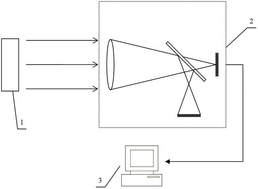
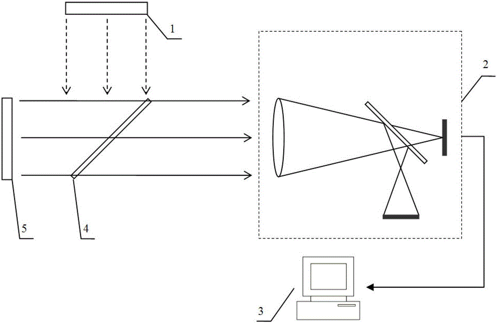
[0025] Such as figure 1 As shown, the plane light wave emitted by the parallel light source 1 is incident on the PD WFS 2; the PD WFS 2 collects the out-of-focus surface spot image and transmits it to the processing system 3; after the processing system 3 obtains the out-of-focus surface far-field spot image The algorithm calculates the amount of defocus of the system.

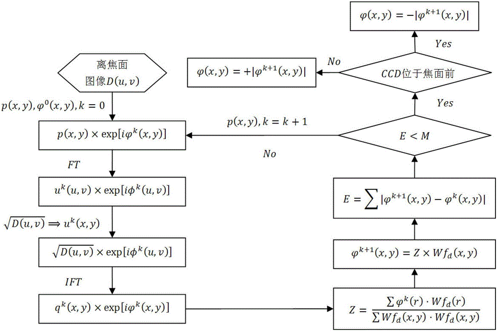
[0026] Such as figure 2 As shown, the defocus amount calculation algorithm starts from obtaining the far-field spot image D(u,v) of the defocus plane, where u,v are the coordinates of the image function definition domain, and the steps are as follows:

[0027] (1) Set loop variable k=0, generalized pupil function p(x,y)=1, initial defocused wavefront It can be any random number, and the pupil surface complex amplitude function is constructed according to the above parameters x, y are the domain coordinates of the wave surface function, and i is the imaginary unit

[0028] (2) Apply Fourier transform...


PUM


Abstract

The invention relates to an off-focus value measuring method for a phase diversity wavefront sensor. By ensuring directional light to enter the phase diversity wavefront sensor (PD WFS), a processing algorithm utilizes an off-focus plane far-field light spot image to restrain the solving process on the basis of the conventional GS iterative operation according to the orthogonality that the off-focus plane only comprises an off-focus phase diversity and a Zernike polynomial, so that the accurate measurement of the off-focus value of a system is implemented. Relative to various current off-focus measuring methods for the PD WFS, the off-focus value measuring method for the PD WFS, which is disclosed by the invention, has the advantages that the structure is simple and stable; the solving process is rapid and reliable; the position of a photoelectric detector CCD (Charge Coupled Device) does not need to be moved in an optical path; other measuring tools are not used; in the iterative process, various prior information is sufficiently utilized to increase the constraint conditions, so that the defect that in a conventional GS algorithm, a correct result cannot be accurately obtained due to the insufficient constraint conditions is overcome; the off-focus value measuring method has higher off-focus value measuring accuracy and stability; and the foundation is laid for the PD WFS toaccurately measure the wavefront phase diversity and recover a degrade image in the actual engineering.

Description

technical field [0001] The invention relates to a method for measuring the defocus amount of a phase difference wavefront sensor. Background technique [0002] The wavefront aberration will distort the wavefront of the incident beam, thereby greatly reducing the resolution and imaging quality of the optical imaging system. Since the 1950s, people have proposed adaptive optics technology (Adaptive Optics, AO), which has effectively improved the imaging quality of optical imaging systems, especially ground-based telescopes. However, limited by the detection accuracy of the wavefront sensor, the limited correction capability of the deformable mirror, and the limited bandwidth of the control loop, the correction of the wavefront distortion by the AO system is partial, and the corrected result is still affected by the residual phase difference. The post-processing method of AO system imaging results has always been a research hotspot in this field. [0003] The phase difference...

Claims


Application Information

Patent Timeline
IPC IPC(8): G01J9/00
Inventor 鲍华饶长辉李梅
Owner INST OF OPTICS & ELECTRONICS - CHINESE ACAD OF SCI
Why Eureka
Eureka Blog
Learn More