
3D four-wheel aligner with no car pushing required

A four-wheel aligner, 3D technology, applied in wheel testing and other directions, can solve the problems of short time, inaccurate data, different data, etc., to achieve the effect of simple use and accurate data

Inactive Publication Date: 2012-10-10
朱迪文
View PDF6 Cites 15 Cited by
  • Summary
  • Abstract
  • Description
  • Claims
  • Application Information

AI Technical Summary

Problems solved by technology

A total of two push carts are required, because the size of the car tires is different, so the tire diameter is different, so the cart distance is different (the cart tires rotate about 20°), if the cart is not in place, or has been pushed, you need to Continue to push until it reaches the desired position, so the operation is very complicated,
[0005] The 3D four-wheel aligner on the market needs to be pushed back about 20° and then forward about 20° when doing car four-wheel alignment. If the push is not in place, it needs to be pushed back and forth multiple times. The operation is complicated and the data is not accurate Through this kind of artificial cart moving back and forth, and through the change of the front and rear positions of the car body, the four-wheel alignment data can be obtained. It can be pushed well in a short time of about 5 minutes, but it may not be pushed well in a long time of more than half an hour, and it cannot be done. tire compensation

Method used


Image

  • 3D four-wheel aligner with no car pushing required
  • 3D four-wheel aligner with no car pushing required
  • 3D four-wheel aligner with no car pushing required

Examples


Embodiment 1

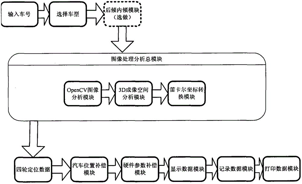
[0029] The main accessories used in this product are a high-configuration computer server and two high-resolution industrial digital cameras. The cameras are fixed at both ends of the camera crossbar. The crossbar is located in front of the car. Perpendicular to lift brackets or trench rails. Keep the crossbar horizontally, and the distance between the crossbar and the center of the lift bracket or the corner plate on the trench track is about 2700mm in the horizontal direction (measured during actual operation). The vertical direction is about 490mm, and the center of the cross bar intersects with the center line of the lift bracket or the trench rail in the front and rear direction of the vehicle as much as possible. In this way, the left and right wheels of the car can be photographed by the two cameras respectively. Target plate fixed to the right rear wheel.

[0030] Because the importance of car front alignment is far greater than rear alignment, so some new cars only ...

Embodiment 2

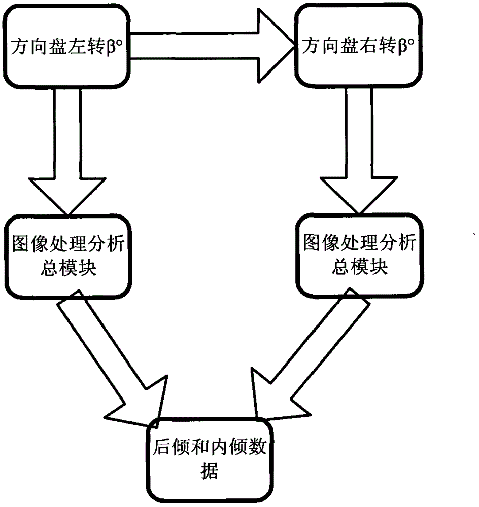
[0041] refer to figure 2 , to measure the inclination and caster angle of the front wheel (optional, because the first is that the inclination test operation is more complicated, and the second is that the steering wheel feels comfortable and does not need to be corrected, so most repairmen do not do this item):

[0042] The inclination angle and caster angle of the front wheel, the inclination angle refers to the angle between the kingpin axis and the tire, and the caster angle refers to the angle between the kingpin axis and the direction of gravity of the earth. The measurement method of the kingpin inclination angle and caster angle is, Click the computer on the positive steering wheel to record the current state of the target wheel, control the camera to capture the image of the target wheel and analyze it, store the analyzed camber and toe-in data in the memory, and then turn the steering wheel to the left to rotate the two front wheels by β° (This degree is known. Ther...

Embodiment 3

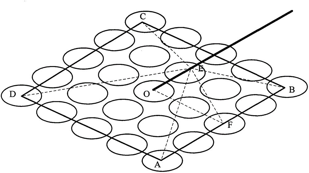
[0044] refer to Figure 5 , Front and rear wheel camber, toe angle test: The camber of the front and rear wheels refers to the angle between the tire and the earth's gravity line. The upper part of the angle is positive when the upper part of the tire is biased outward, and negative if it is biased inward. The toe angle of the front and rear wheels refers to the angle between the tire and the front and rear direction of the car. The front of the tire is positive inward and negative inward. Since the target disc is clamped on the tire rim by a high-precision four-claw clamp, Through the space position of the target disc calculated above, the camber and toe-in of the target disc can be obtained, then the camber and toe-in of the car tires are the corresponding camber and toe-in of the target disc.

[0045] First, control the camera to capture the color picture of the target disk in the camera, and use opencv to convert the color picture into a black and white picture. Then obta...


PUM


Abstract

The invention discloses a 3D four-wheel aligner with no car pushing required, comprising an image processing and analyzing general module, a vehicle position compensation module, a hardware parameter compensation module, two cameras and four target disks with regular patterns. The 3D four-wheel aligner with no car pushing required is capable of overcoming the defect that a 3D four-wheel aligner with car pushing required is complex in operation. A test can be carried out directly once the target disks are hung, with no car pushing required. The operation is very simple and the data is more accurate. In view of the characteristic that the 3D four-wheel aligner with car pushing required in the market is complex in cart pushing, the 3D four-wheel aligner with no car pushing required in the invention is capable of carrying out measurement directly once the target disks are installed, with no cart pushing required. The technology adopted in the 3D four-wheel aligner with no car pushing required in the invention is totally different from that of the 3D four-wheel aligner with car pushing required, wherein the 3D four-wheel aligner with car pushing required uses position change of the target disks before and after cart pushing to calculate vehicle four-wheel alignment data, while the 3D four-wheel aligner with no car pushing required in the invention uses space structure of the target disks to calculate the vehicle four-wheel alignment data.

Description

technical field [0001] The invention relates to the technical field of four-wheel alignment of automobiles, in particular to a 3D four-wheel alignment device that does not require a cart. Background technique [0002] The four wheel aligners that are common in the market now are mainly laser and 3D, and others include PSD and CCD. [0003] The PSD four-wheel aligner is an old-fashioned traditional four-wheel aligner. It uses the characteristic that the laser beam propagates in a straight line in the air. The main accessories of the equipment are four sensors, each of which can receive and emit laser light, and the car can carry out During the four-wheel alignment monitoring, four sensors are hung on the four tires, the laser of the sensor on the left hits the sensor on the right, and the photosensitive part of the sensor converts the light signal into a position signal and inputs it to the computer to complete the positioning Monitoring, in the same way, the laser light of ...

Claims


Application Information

Patent Timeline
Patent Type & Authority Applications(China)
IPC IPC(8): G01M17/013
Inventor 朱迪文
Owner 朱迪文
Learn More