
Micro-turbine combustor

A turbine and combustor technology, applied in the field of self-sustained cogeneration plants, can solve the problems of inability to remove carbon deposits, blockage of fuel delivery systems, and ineffective deposits

Inactive Publication Date: 2012-10-10
JHRG公司
View PDF7 Cites 1 Cited by
  • Summary
  • Abstract
  • Description
  • Claims
  • Application Information

AI Technical Summary

Problems solved by technology

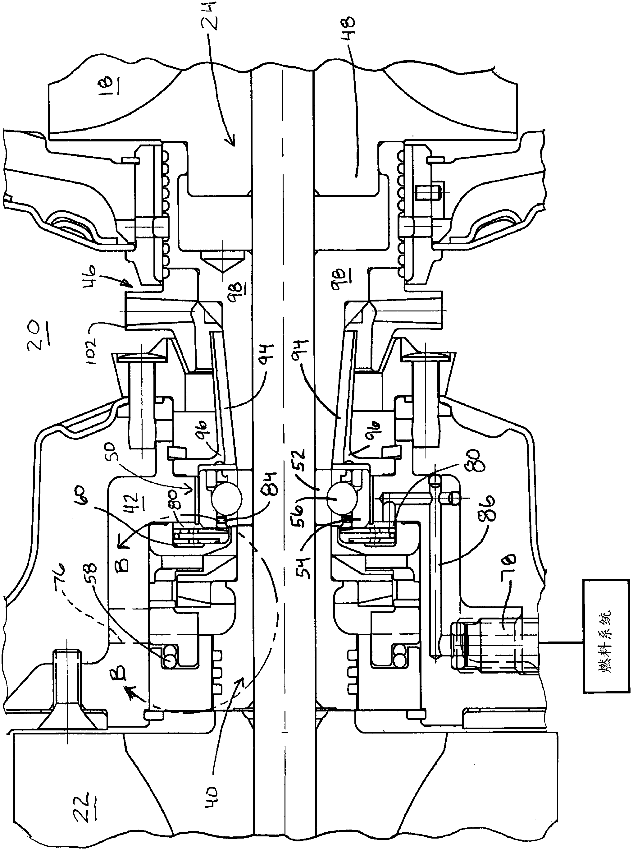
[0006] During prolonged operation under extreme conditions, carbon deposits have been found to form in the fuel deflector, flinger body and flinger assembly and cannot be removed
Traditional solutions to this problem are ineffective in removing these deposits, which eventually lead to clogging within the fuel delivery system

Method used


Image

  • Micro-turbine combustor
  • Micro-turbine combustor
  • Micro-turbine combustor

Examples


Embodiment Construction

[0025] Example embodiments will now be described more fully with reference to the accompanying drawings. Example embodiments are provided so that this disclosure will be thorough, and will fully convey the scope to those who are skilled in the art. Numerous specific details are set forth, such as examples of components, devices, and methods, in order to provide a thorough understanding of embodiments of the present disclosure. It will be apparent to those skilled in the art that specific details need not be employed, that example embodiments may be embodied in many different forms and that neither should be construed to limit the scope of the disclosure. In some example embodiments, well-known methods, well-known device structures, and well-known technologies are not described in detail.

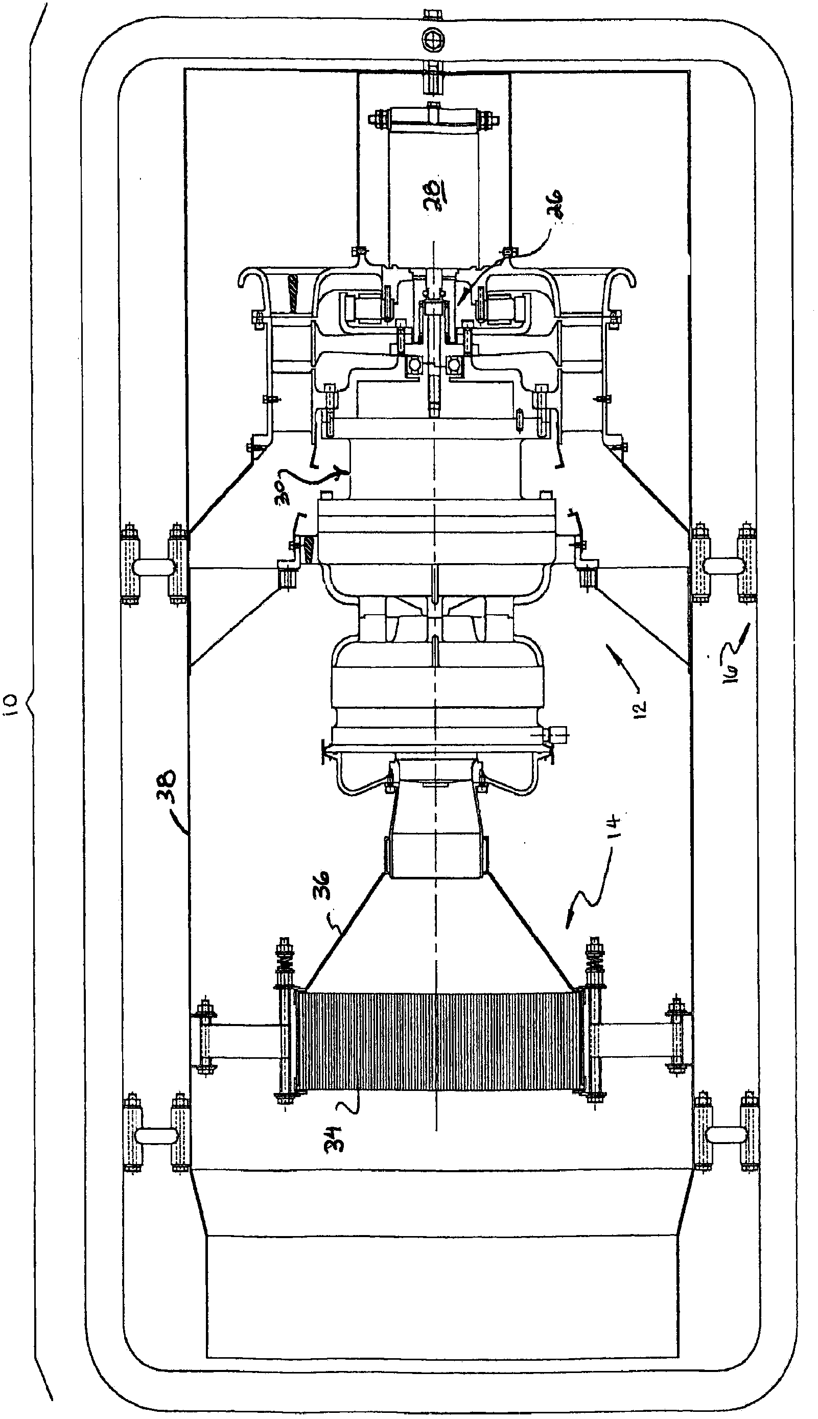
[0026] now refer to figure 1 As in FIG. 2 , a combined heat and power plant or turbine heater 10 includes a gas turbine engine 12 and a catalytic heat exchange element 14 supported within ...


PUM


Abstract

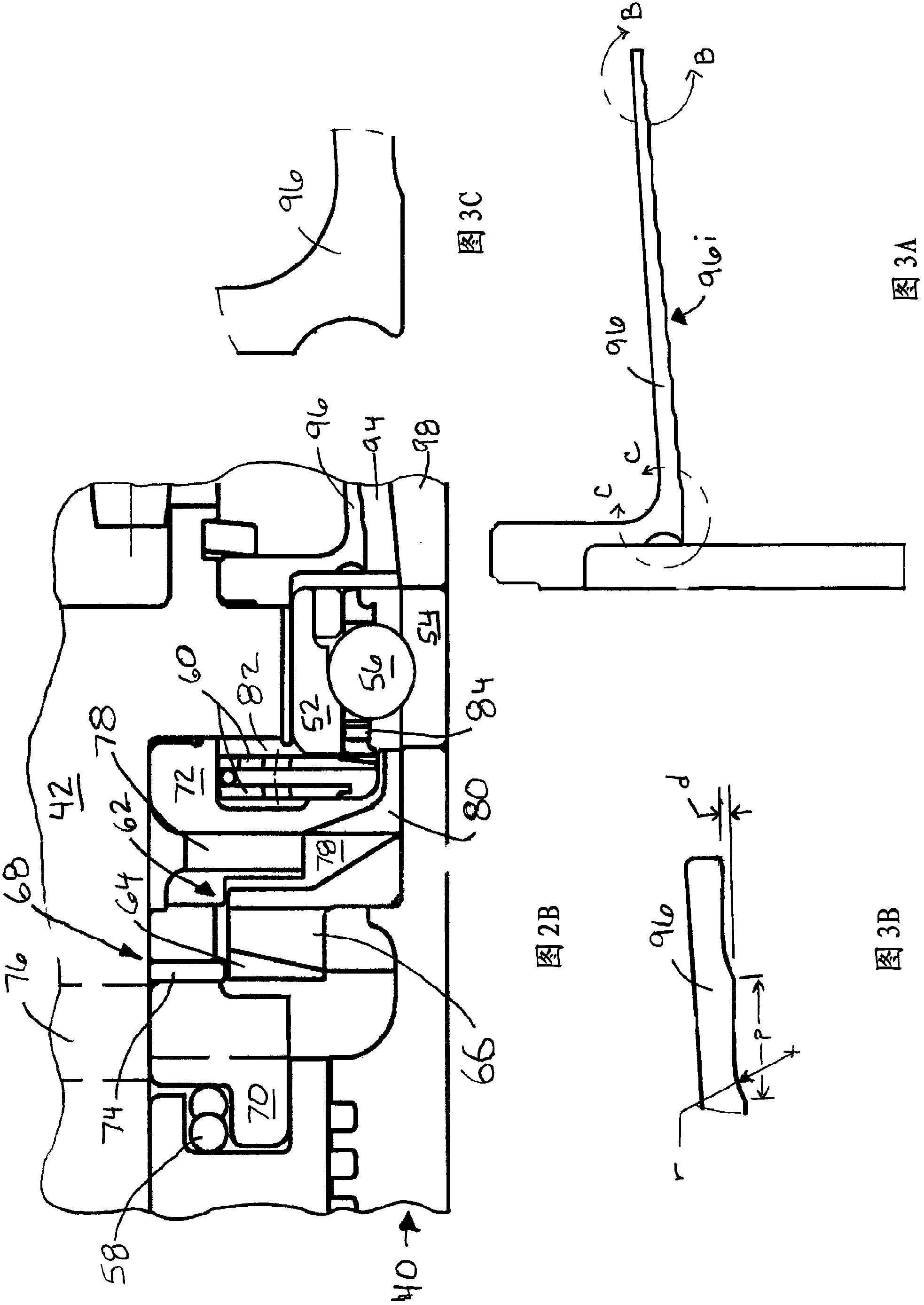
A micro gas turbine engine for use in a turbo heater or co-generation application is described. The micro gas turbine engine includes a fuel delivery system which minimizes the development of deposits in the air-fuel passageway. To this end, a fuel delivery channel formed between a fuel deflector and a slinger body is formed with a contoured or undulating surface. A fuel deflector ring is interposed between the fuel delivery channel and the slinger impeller to facilitate the flow of the air-fuel mixture into the combustion chamber.

Description

technical field [0001] The present disclosure relates to a self-sustaining combined heat and power plant utilizing a micro gas turbine engine to provide heated air through a heat exchanger, a catalyst or an open flame and for generating a rotary drive capable of powering an auxiliary generator, and more specifically, The present invention relates to an improved fuel deflector / slinger assembly for a microturbine engine that minimizes the accumulation of particulates within a fuel delivery system. Background technique [0002] This section provides background information related to the present disclosure which is not necessarily prior art. [0003] Recent efforts have shown that micro gas turbine engines can be used in combined heat and power plant applications to provide heat and auxiliary power. In particular, small gas turbines have proven to be light, relatively trouble-free and extremely efficient, making them excellent heaters. Exemplary embodiments of generator sets e...

Claims


Application Information

Patent Timeline
Patent Type & Authority Applications(China)
IPC IPC(8): F02C3/14F02C7/22F02C6/18F01D9/02
CPCF02C7/22F23C2900/03001F05D2250/82F02C3/14Y02E20/14
Inventor 理查德·W·戈登(已逝)
Owner JHRG公司
Learn More