
Circulating type automatic iron removing machine

A circulating type iron remover technology, applied in the direction of magnetic separation, solid separation, chemical instruments and methods, etc., can solve the problems of magnetic medium adsorption accumulation, inability to clean in time, unfavorable adsorption of iron impurities, etc., to improve adsorption capacity , Simple structure, complete effect of iron removal

Inactive Publication Date: 2014-09-24
廖明勇
View PDF7 Cites 0 Cited by
  • Summary
  • Abstract
  • Description
  • Claims
  • Application Information

AI Technical Summary

Problems solved by technology

[0005] 3. The magnetically conductive medium itself cannot rotate, resulting in the effective removal of iron by the magnetically conductive medium, which is not conducive to the complete adsorption of iron impurities, but also causes the magnetically conductive medium to absorb too much locally and accumulate, which greatly affects the adsorption effect;
[0006] 4. The magnetic medium cannot be cleaned in time after absorbing iron impurities. When a large amount of powder iron removal work is required, the iron impurities accumulated on the magnetic medium are not conducive to continuous and thorough adsorption of iron impurities sent into the powder. , will also cause incomplete iron removal

Method used


Image

  • Circulating type automatic iron removing machine
  • Circulating type automatic iron removing machine

Examples


Embodiment Construction

[0018] The content of the invention will be further described below in conjunction with the accompanying drawings and embodiments.

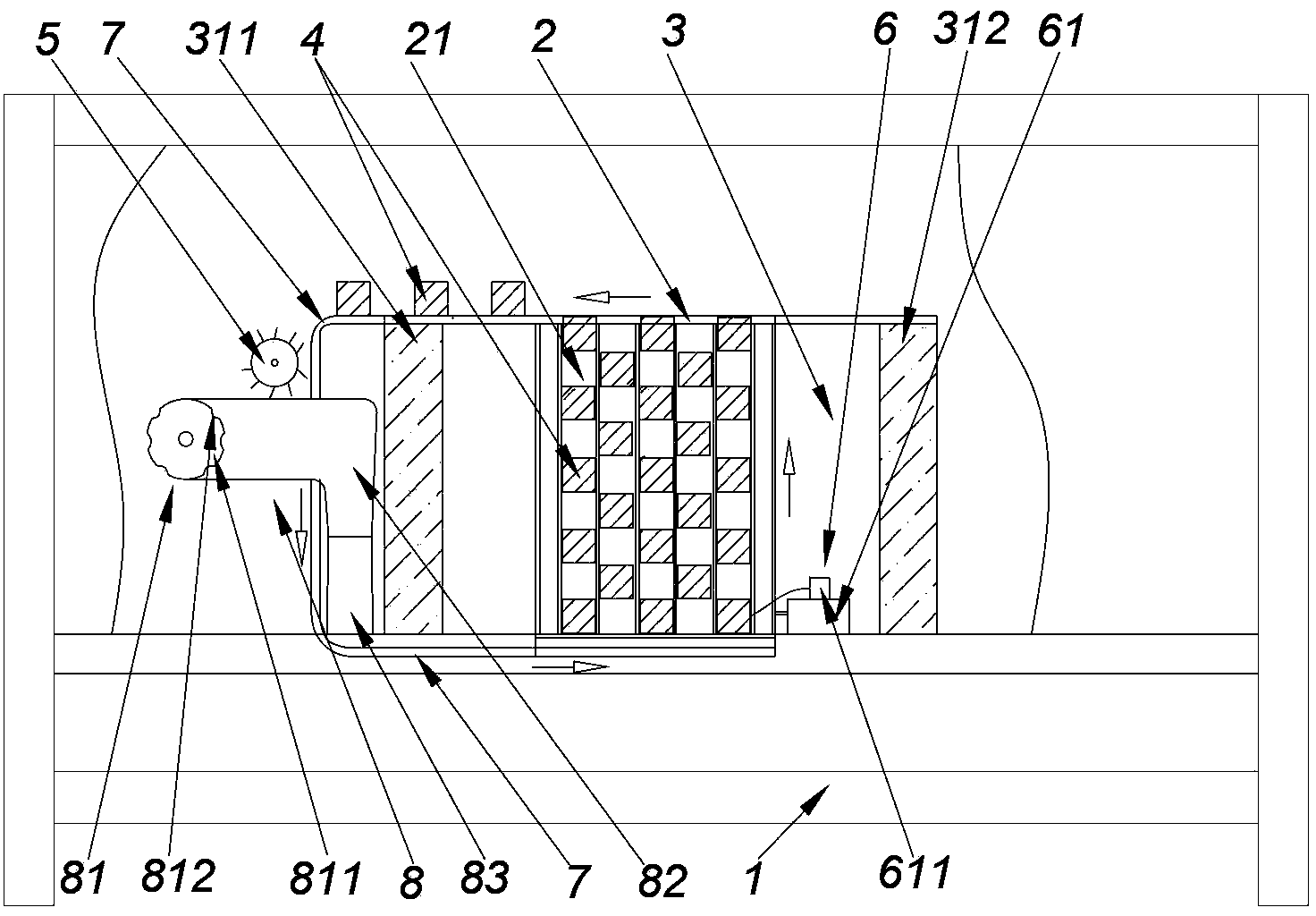
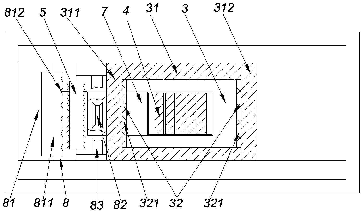
[0019] Such as figure 1 , 2 As shown, the iron remover of this embodiment includes a frame 1, on which a working chamber 2 and a magnetic region 3 are installed, the working chamber 2 is surrounded by the magnetic region 3, and the surroundings of the magnetic region 3 are closed by four soft magnetic bodies 31. Up and down openings, a set of permanent magnet groups 32 are arranged on the soft magnet 31, and the permanent magnet group 32 includes a pair of permanent magnets 321 with different poles facing each other. The permanent magnets 321 are respectively arranged on the left soft magnet 311 and the right soft magnet 312. Above, the permanent magnet 321 will generate a magnetic field in the magnetic zone 3, and the non-named magnetic poles between the permanent magnets 321 form a closed magnetic circuit with continuous magnetic flux circulat...


PUM


Abstract

The present invention relates to a circulating type automatic iron removing machine. With the circulating type automatic iron removing machine, a magnetic region used for magnetic separation is designed into a structure with a closed periphery to gather magnetic induction lines and form a closed magnetic circuit of magnetic induction line circulation, circulation of the magnetic induction lines inside the magnetic region is adopted to enhance magnetic field strength, and a clean problem of a magnetic conductive media after iron impurity absorption is effectively solved. The magnetic region is formed by semi-enclosing a soft magnet, wherein the soft magnet is provided with a permanent magnet, the synonym poles of the permanent magnet are located oppositely, and a working chamber is arranged in the magnetic region. The exterior of the magnetic region is provided with a brush body. A pushing device for pushing the magnetic conductive media and a transimisson device for conveying the magnetic conductive media to generate friction between the magnetic conductive media and the brush body are mounted on the working chamber, wherein the pushing device and the working chamber form a head-tail connection. The circulating type automatic iron removing machine of the present invention has characteristics of simple structure, low cost, and high automation degree, and can be widely used in fields of dry powder iron removing and ceramic. With the circulating type automatic iron removing machine of the present invention, iron can be removed completely, and cleaning is performed completely.

Description

technical field [0001] The invention relates to dry powder iron removal and iron removal equipment in the ceramic industry, in particular to a circulating automatic iron remover. Background technique [0002] Dry powder iron removal and raw materials in the ceramic industry contain ferromagnetic substances, and ferromagnetic substances will seriously affect the whiteness of the product, and will also form defects such as black spots, melting holes, and impurities on the surface of the product, resulting in product quality defects. Therefore, the dry powder iron removal and the ceramic industry have very high technical requirements for the selected iron removal equipment, but the existing iron removal equipment still has the following problems in terms of the thoroughness of iron removal and the cleanliness of the magnetic medium: [0003] 1. The magnetic regions formed by the magnets are open. Although the magnetic field lines of the adjacent magnetic regions can be superimp...

Claims


Application Information

Patent Timeline
Patent Type & Authority Patents(China)
IPC IPC(8): B03C1/02
Inventor 廖明勇
Owner 廖明勇
Learn More