Lens heat effect measuring system and measuring method

A measurement system and thermal effect technology, applied in the field of photolithography, can solve the problems of thinner graphics lines, invisible lines, high sensor cost, etc., and achieve the effect of high process applicability and low cost

Inactive Publication Date: 2012-10-17
SHANGHAI MICRO ELECTRONICS EQUIP (GRP) CO LTD
View PDF5 Cites 5 Cited by
  • Summary
  • Abstract
  • Description
  • Claims
  • Application Information

AI Technical Summary

Problems solved by technology

[0006] 1. When the silicon wafer is heated, it is easy to deform, resulting in inaccurate sampling data;
[0007] 2. Continuous exposure to the field points will make the lines of the graph thinner, and the lines will break in some places, and even the lines will not be visible;
[0008] 3. The stray light of the lighting system is very strong, which will also cause image pollution on the silicon wafer
[0011] 1. The measurement accuracy of the sensor must be high enough, which also causes the sensor to be too expensive;
[0012] 2. There is a one-to-one correspondence between the measurement mark and the sensor, so when measuring the thermal effect, the type of mark that can be used is single;

Method used


Image

  • Lens heat effect measuring system and measuring method
  • Lens heat effect measuring system and measuring method
  • Lens heat effect measuring system and measuring method

Examples


no. 1 example

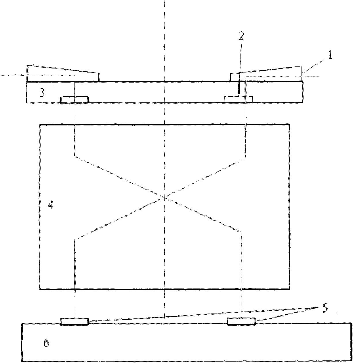
[0039] The structure diagram of the thermal effect measurement system used in the method for measuring the thermal effect of the lens by using the machine vision system according to the present invention is as follows figure 1 As shown, the equipment includes: a mask table reference plate 1 , a mask / mark on the mask table 2 , a mask 3 , a projection objective lens 4 , a machine vision system (MVS) 5 and a workpiece table 6 .

[0040] The basic method of using this equipment to test the thermal effect is: project the mark 2 on the mask / mask stage onto the workpiece stage 6 through the projection objective lens 4, measure the change of the position of the mark with time by the MVS5 on the workpiece stage 6, and collect the time And position information until the thermal equilibrium state (it takes several hours), find out the relationship between time and image quality parameter changes through mathematical methods, that is, the thermal effect scaling factor and time constant.

...

no. 2 example

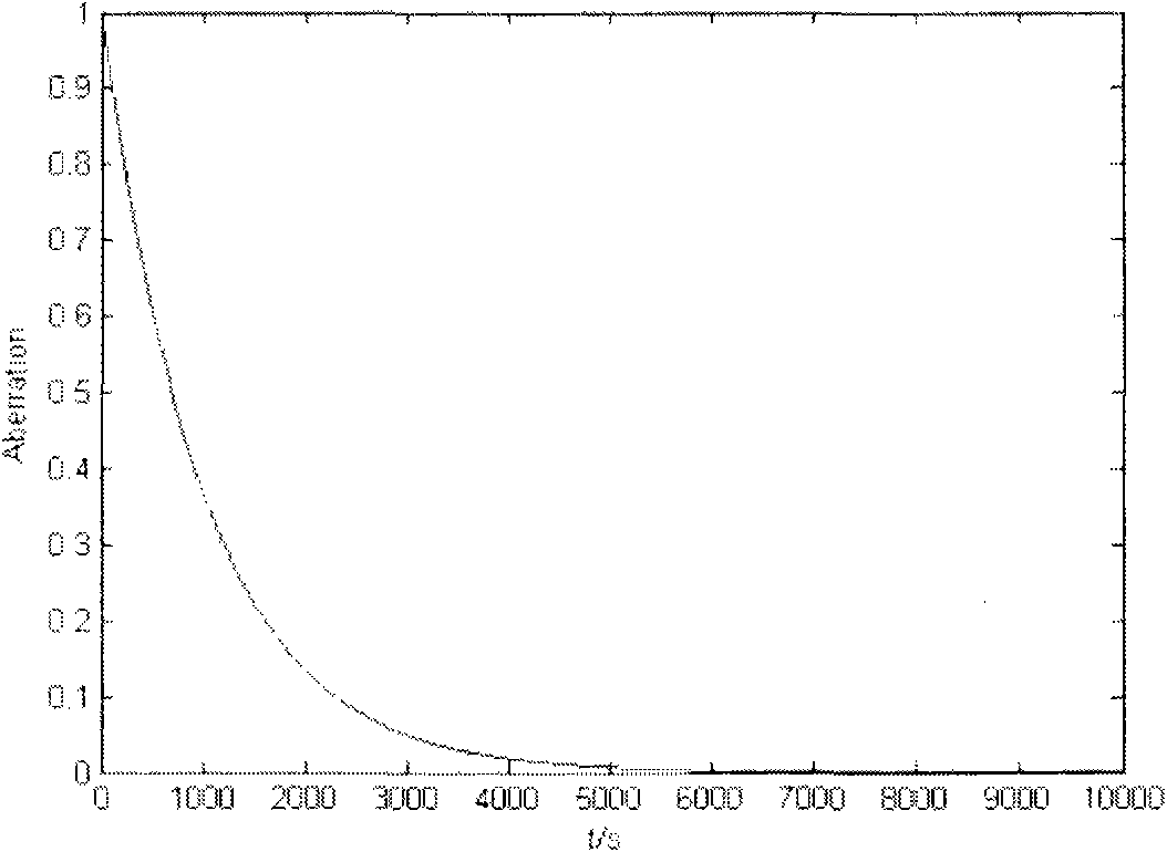
[0063] In this embodiment, the test of the descending curve is carried out. Such as image 3 As shown, where the horizontal axis represents the test time, and the vertical axis represents the image quality change (normalized). The thermal effect curve changes rapidly in the initial stage of measurement, and basically reaches saturation after about 5000s. Since the thermal effect scaling factor and time constant of the lens have the same effect on the rising curve and the falling curve, the falling curve can also be used to test the thermal effect, and the rising and falling curves can be used to verify each other.

[0064] This test consists of the following steps (since this method is used for a drop curve, it requires the lens to be "hot" at the beginning):

[0065] Use the strategy of first tightening and then loosening to select the test sampling time point;

[0066] Check the status of subsystems: whether MVS, mask / mask table reference plate, workpiece table, etc. are ...


PUM


Abstract

The invention discloses a lens heat effect measuring system which comprises a mask, an object marker, a lens to be measured, and a workpiece table sequentially along the direction of light transmission, and further comprises at least one machine vision system. The at least one machine vision system is located on the workpiece table. Light emitted from the object marker is imaged on the at least one machine vision system through the lens to be measured. The invention further discloses a lens heat effect measuring method.

Description

technical field [0001] The invention relates to the field of lithography, in particular to a lens thermal effect measurement system and a measurement method using a machine vision system in the field of lithography. Background technique [0002] During the exposure process, the thermal effect of the lens is a very important factor leading to the deterioration of image quality. The thermal effect of the lens refers to: due to the heat absorption of the lens during the exposure process, a small deformation occurs, which makes some optical parameters of the lens (such as magnification, distortion, defocus, wave aberration, etc.) deviate from its design value. When the exposure dose requirement becomes larger and the lens continues to absorb heat during the continuous exposure of the silicon wafer, this deformation will be more obvious. Therefore, the thermal effect of the lens must be corrected. [0003] There are currently two ways to measure the thermal effect of the lens: o...

Claims


Application Information

Patent Timeline
Patent Type & Authority Applications(China)
IPC IPC(8): G01M11/02G03F7/20
Inventor 冯盛马明英
Owner SHANGHAI MICRO ELECTRONICS EQUIP (GRP) CO LTD
Why Eureka
Try Eureka