
Core-adjustable variable-cross-section-tube ultrasonic condensation cyclone separator

A cyclone separator and supersonic technology, which is applied in the fields of expansion refrigeration and condensation separation of pressurized gas, can solve the problems of pressure energy loss, poor adaptability to changing working conditions, and reduced gas-liquid separation effect, etc. The effect of increasing and strong centrifugal separation capacity

Inactive Publication Date: 2012-10-24
DALIAN UNIV OF TECH
View PDF10 Cites 19 Cited by
  • Summary
  • Abstract
  • Description
  • Claims
  • Application Information

AI Technical Summary

Problems solved by technology

[0004] However, the above supersonic condensation cyclone separators all have a throat section with a fixed area. When the pressure ratio between the inlet and outlet, especially the condensate discharge pressure, deviates from the design, shock waves will be generated in the separation pipe, which not only causes The loss of pressure energy and the heating effect of the shock wave will cause the condensed atomized liquid droplets to re-evaporate, reducing the effect of gas-liquid separation
Therefore, the poor adaptability to changing working conditions is a great weakness of the supersonic condensation cyclone separator

Method used


Image

  • Core-adjustable variable-cross-section-tube ultrasonic condensation cyclone separator
  • Core-adjustable variable-cross-section-tube ultrasonic condensation cyclone separator
  • Core-adjustable variable-cross-section-tube ultrasonic condensation cyclone separator

Examples


Embodiment approach

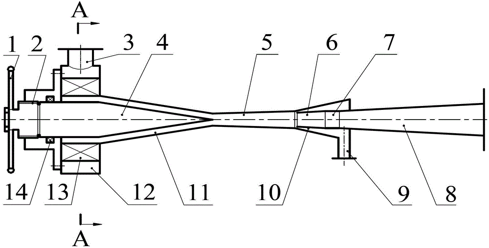
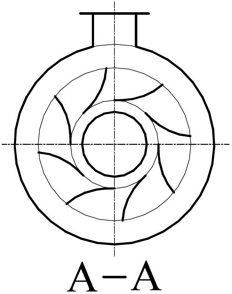
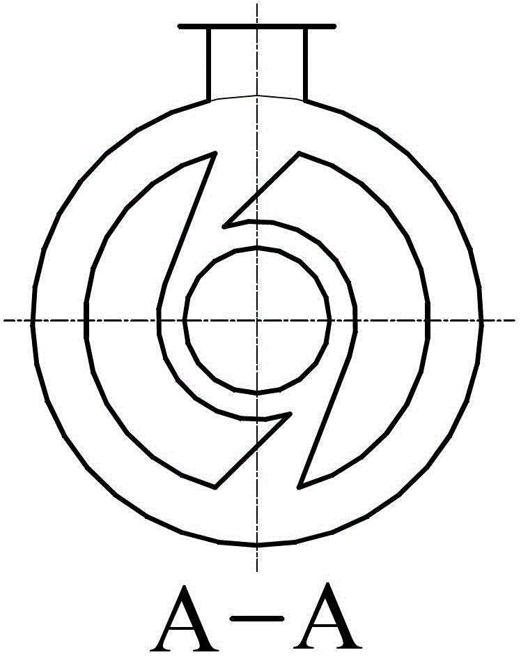
[0031] see figure 1, core-adjusting supersonic condensing cyclone separator, mainly composed of adjusting handle 1, screw inlet and outlet unit 2, gas inlet pipe 3, adjusting cone core 4, nozzle supersonic section 5, stabilizing cone section 6, nozzle deceleration straight Section 7, diffuser section 8, condensate outlet pipe 9, condensate outlet chamber 10, nozzle accelerating swirl section 11, intake buffer chamber 12, pre-swirl unit 13 and packing static seal 14.

[0032] In the central axis area of ​​the accelerated swirling section 11 of the nozzle of the cyclone separator, place an adjusting cone core 4 whose axis coincides with the axis of the nozzle and whose position can move forward and backward, and turn the adjusting handle 1 to drive the screw in and out of the unit 2 , the adjusting cone core 4 is moved inwardly or outwardly along the axis, causing the cross-sectional area of ​​the annular flow channel of the nozzle accelerating swirling section 11 to change cont...


PUM

PropertyMeasurementUnit
angleaaaaaaaaaa
lengthaaaaaaaaaa
diameteraaaaaaaaaa

Abstract

The invention provides a core-adjustable variable-cross-section-tube ultrasonic condensation cyclone separator, which belongs to the technical field of expansion refrigeration and condensation separation for pressurized gas. A position-adjustable conical core is inserted into an axial area of an acceleration flow channel of a jet pipe, which enables the cross section of the throat of the jet pipe to be changed; therefore, changes of pressure at an inlet and an outlet of the separator can be adapted, shock waves are not generated at an ultrasonic centrifugation section of the flow channel, condensed liquid drops are heated and evaporated, and high variable-condition efficiency is obtained. At a subsonic accelerating spinning-improving section of the jet pipe, an axle center zone is occupied by the adjustable conical core to form an annular cross-section flow channel which has a greater diameter contraction ratio, is more powerful in improving spinning and has greater capacity in centrifugation. According to the invention, the condensation cyclone separator realizes expansion, cooling and condensation by utilizing pressure of gas, strengthens spinning through diameter contraction, separates condensate through centrifugation and enables pressure to isentropically recover later. The condensation cyclone separator has the advantages of no moving members, high pressure resistance, no need for external driving, conservation of energy, a small volume, low cost, reliable operation, etc., and is applicable to mixed gas, e.g., separation of heavy components in natural gas and petroleum gas.

Description

technical field [0001] The invention belongs to the technical field of expansion refrigeration and condensation separation of pressurized gas. The core-adjustable variable cross-section tube supersonic condensation cyclone separator of the present invention is an ultra-small high-efficiency static condensation separation device that can expand the gas to increase the speed and cool down, and at the same time generate a high-speed rotating flow field to centrifugally separate the heavy component condensate . Background technique [0002] The pressure energy of the pressure gas itself is used to expand and refrigerate, so that the heavy components in it are condensed into liquids, and then the gas-liquid separation is carried out to realize the extraction of the heavy components in the mixed gas. This process is widely used in the separation of various mixed gases, especially in the fields of natural gas dehydration purification and light hydrocarbon recovery. [0003] Press...

Claims


Application Information

Patent Timeline
Patent Type & Authority Applications(China)
IPC IPC(8): B04C3/00B04C3/02B04C3/06B01D5/00B01D45/16
Inventor 胡大鹏邹久朋刘培启朱彻代玉强刘凤霞
Owner DALIAN UNIV OF TECH
Learn More