Horizontal lathe for machining cylindrical eccentric part and method adopted by same

A horizontal lathe, eccentric technology, applied in the direction of metal processing machinery parts, cutting tools for lathes, metal processing equipment, etc., can solve the problem that it is difficult to ensure the processing quality of parts in the complex processing process of products, and the processing control of eccentric holes is difficult to determine by cutting tool design Difficult to implement, low processing accuracy and processing efficiency, etc., to achieve the effect of improving stability and processing accuracy, improving cutting efficiency, and reducing tool weight

Inactive Publication Date: 2012-10-24
NFC (SHENYANG) METALLURGICAL MACHINERY CO LTD
View PDF4 Cites 17 Cited by
  • Summary
  • Abstract
  • Description
  • Claims
  • Application Information

AI Technical Summary

Problems solved by technology

[0003]Because the length of the cylindrical taper sleeve is too long, the diameter of the eccentric taper hole is too small, the machining axis of the inner hole is different from the machining axis of the outer circle, and the inner hole One side is tapered at 1:24, which makes the processing of the inner taper hole and outer circle of the eccentric sleeve more complicated
[0004] Whether the traditional method is to process the inner hole or the outer circle first, it is difficult to determine the design of the tool and control the machining of the eccentric hole
Under normal circumstances, deep hole processing is mostly completed by drilling, reaming and boring on a drilling machi

Method used


Image

  • Horizontal lathe for machining cylindrical eccentric part and method adopted by same
  • Horizontal lathe for machining cylindrical eccentric part and method adopted by same
  • Horizontal lathe for machining cylindrical eccentric part and method adopted by same

Examples


Embodiment Construction

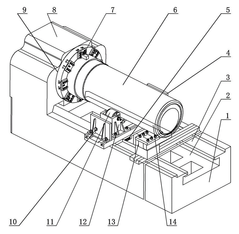
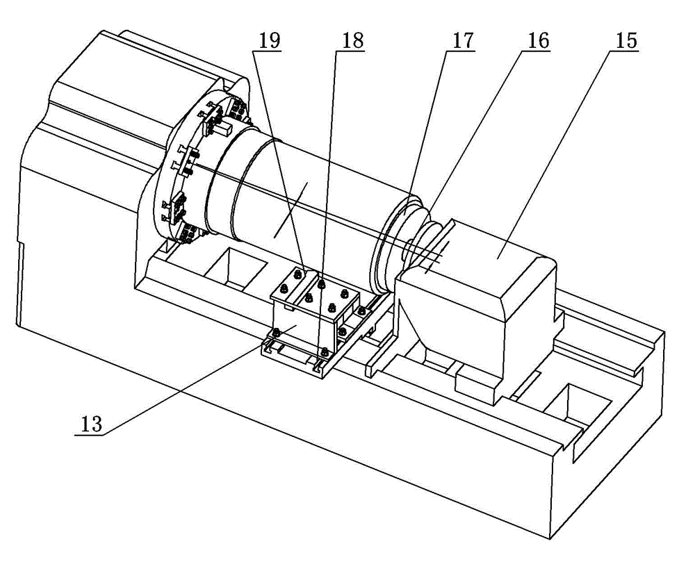
[0036] Such as figure 1 Shown is a schematic diagram of the structure of the horizontal lathe 1 of the present invention when machining the inner hole; in the figure, the axis of the main shaft of the horizontal lathe 1 is the X direction, and the direction perpendicular to the bed 2 of the horizontal lathe 1 is the Z direction and the Y direction Perpendicular to the X and Z directions. The left side of horizontal lathe 1 is bed head 8, and the right side is bed tail 15 (in figure 1 Not shown in the figure), between the head of the bed 8 and the end of the bed 15 is a horizontal bed 2. The inboard of head of bed 8 is provided with chuck 9, and jaw 7 is arranged on chuck 9, and among the figures, jaw 7 is eight, and chuck 9 is equally divided, and the effect of chuck 9, jaw 7 is to make cylinder class The eccentric sleeve part 6 is clamped and fixed on the head of the bed 8, so that it rotates with the chuck 9 under the drive of the main shaft of the horizontal lathe 1;...


PUM


Abstract

The invention provides a horizontal lathe for machining a cylindrical eccentric part and a method adopted by the horizontal lathe, which relate to a machining mechanism for machining the cylindrical eccentric part, in particular to a horizontal lathe for machining the cylindrical eccentric part and a machining method of the cylindrical eccentric part. Through the horizontal lathe and the machining method, the machining efficiency and the machining accuracy of the cylindrical eccentric part are improved; the production cost is reduced; the machining of the cylindrical eccentric part by the horizontal lathe is realized; and the needs for machining the cylindrical eccentric parts with different specifications and lengths are satisfied. The horizontal lathe comprises a horizontal lathe, and one side of a lathe body of the horizontal lathe is provided with a lathe headstock and the other side thereof is provided with a lathe tailstock; the lathe headstock is provided with a clamping disk with clamping jaws; correspondingly, the lathe tailstock is provided with a tip; and a tool feed rest is arranged on a guide rail of the lathe body between the lathe headstock and the lathe tailstock. The horizontal lathe has structural key points as follows: a roller support transmission combined with the guide rail of the lathe body is arranged; and the tool feed rest is used for fixing an excircle turning tool or an inner-hole turning tool.

Description

technical field [0001] The invention relates to a processing mechanism for cylindrical eccentric parts, more specifically, to a horizontal lathe for processing cylindrical eccentric parts and a processing method for the cylindrical eccentric parts. Background technique [0002] Cone crusher is an ore crusher developed in the last century. It has the characteristics of simple structure, convenient control, large crushing particle size, easy disassembly and maintenance, and is widely used in mining and metallurgy and other fields. Cylindrical eccentric parts-eccentric sleeve assembly is the main part of the cone crusher to complete the crushing. Generally, the eccentric sleeve assembly is mainly composed of eccentric shaft, eccentric sleeve, key, cage, gear, and gear mounting frame. [0003] Due to the length of the cylindrical tapered sleeve is too long, the diameter of the eccentric taper hole is too small, the machining axis of the inner hole is not the same axis as the mac...

Claims


Application Information

Patent Timeline
IPC IPC(8): B23B5/00B23B23/00B23B27/00B23Q3/00
Inventor 刘红枫蒋晓妍徐雁凯黄浩赵志张世军胡秀芬
Owner NFC (SHENYANG) METALLURGICAL MACHINERY CO LTD
Why Eureka
Try Eureka