
Hybrid power driving system

A drive system, hybrid technology, applied in hybrid vehicles, power plants, pneumatic power plants, etc., can solve the problems of reduced energy efficiency, large energy loss, low transmission efficiency, etc., to shorten the axial distance, improve Energy efficiency, the effect of reducing energy loss

Inactive Publication Date: 2012-10-24
TIANJIN SANTROLL ELECTRIC AUTOMOBILE TECH CO LTD
View PDF7 Cites 5 Cited by
  • Summary
  • Abstract
  • Description
  • Claims
  • Application Information

AI Technical Summary

Problems solved by technology

[0004] The hybrid driving device disclosed in the above-mentioned patent documents adopts the second electric motor to start or move when starting or at low speed. When the speed is further increased, the engine and the second electric motor are used for hybrid driving. Improvement, when the engine is in the high-efficiency operation zone, when the motor is no longer needed, the power of the engine still needs to be transmitted through the planetary gear, and the energy loss of the transmission is large. For large vehicles that are in this speed range most of the time, such as city buses, Because the economy affected by this part of the energy loss is very important; and according to the different materials and manufacturing processes of the planetary gears, the energy loss of the engine energy through the planetary gears is different, and the larger the transmission ratio, the lower the transmission efficiency and energy. consume more
[0005] Vehicles that often work at low speeds (such as urban buses or special vehicles for temporary operations) generally use different engines from small vehicles. When the engine of the system is in the high-efficiency zone, it still needs to be transmitted through the planetary gear, which reduces the energy efficiency. Therefore, if the vehicle that is often running at low speed uses the above-mentioned hybrid drive device, it is difficult to make this type of vehicle be in the high-efficiency running zone, so the energy loss is large. Conducive to energy saving

Method used


Image

  • Hybrid power driving system
  • Hybrid power driving system
  • Hybrid power driving system

Examples


Embodiment Construction

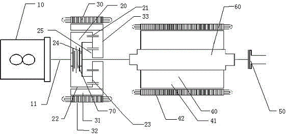
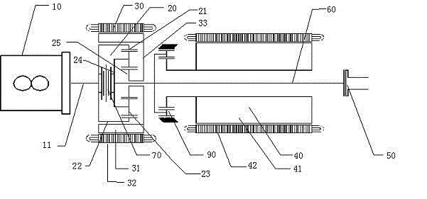
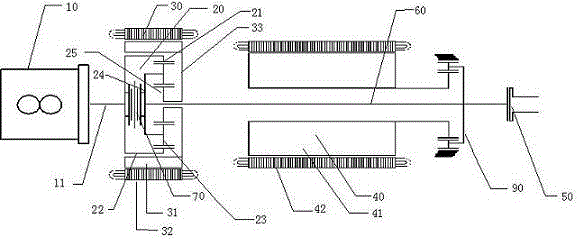
[0030] figure 1 Shown is a hybrid drive system described in this embodiment, including

[0031] an engine 10 having an output shaft 11;

[0032] A planetary gear mechanism 20, which includes a ring gear 21, a plurality of planetary gears fixed coaxially with the output shaft 11 at the center of the ring gear 21, a plurality of planetary gears internally meshed with the ring gear 21, and planetary gears fixed with the planetary gear 23 The carrier 24 and the sun gear 25 externally meshed with the planetary gear 23;

[0033] The generator 30 has a generator rotor 31 and a generator stator 32, and the generator rotor is coaxially fixed with the sun gear 25. In this embodiment, the generator rotor 31 is provided with a fixing device 33. The fixing device 33 is fixed coaxially with the sun gear 25, and the fixing device may be a fixing bracket;

[0034] The motor 40 has a motor rotor 41 and a motor stator 42, the motor rotor 41 is connected with the planet carrier 24 through an ...


PUM


Abstract

The invention relates to a hybrid power driving system, comprising an engine, a planet gear mechanism, a generator and a motor, wherein the engine is provided with an output shaft, the planet gear mechanism comprises a gear ring, a planet frame and a sun gear, the gear ring is connected with the output shaft of the engine, the generator is provided with a generator rotor, the generator rotor is coaxially fixed with the sun gear, the motor is provided with a motor rotor, the motor rotor is connected with the planet frame by virtue of a middle shaft; and a clutch device is arranged between the gear ring and the planet frame. The invention solves the problems that transmission energy loss of the planet gear in an engine hybrid operating mode is high in the series-parallel hybrid power system and a vehicle which is frequently in low-speed traveling operating state is difficult to be located in an high-efficiency operation region in the prior art and further provides a series-parallel hybrid power system which is applicable to a vehicle frequently in low-speed traveling operating state and can cause the vehicle to be located in the high-efficiency operation region.

Description

technical field [0001] The invention relates to a vehicle power drive system, in particular to a hybrid drive system. Background technique [0002] There are three types of hybrid drive systems: series, parallel and hybrid. The series hybrid power system first converts all the power output by the engine into electrical energy by the generator, and then converts the electrical energy into mechanical energy to drive the wheels through the electric motor. Its advantage is that it can realize the optimal control of the engine, and its disadvantage is that after two energy conversions, The energy loss is large. The parallel system is based on the traditional car transmission system, plus an electric drive system to provide auxiliary power for the car when accelerating or climbing. In the existing series hybrid system, the internal combustion engine system and the motor drive system each have a set of mechanical transmission mechanisms, and the two mechanisms are combined throug...

Claims


Application Information

Patent Timeline
IPC IPC(8): B60K6/44B60K6/365B60K6/26
CPCY02T10/6243Y02T10/623Y02T10/62
Inventor 静占国
Owner TIANJIN SANTROLL ELECTRIC AUTOMOBILE TECH CO LTD
Learn More