
Movable solar shower system

A shower system and solar energy technology, applied in solar thermal power generation, showers, solar thermal devices, etc., can solve the problems of wasting cold water, power consumption or gas consumption, and not saving hot water, etc., so as to reduce heat loss and use The effect of long life and easy overall handling

Active Publication Date: 2012-10-24
SHENZHEN INST OF BUILDING RES
View PDF7 Cites 1 Cited by
  • Summary
  • Abstract
  • Description
  • Claims
  • Application Information

AI Technical Summary

Problems solved by technology

Practice has proved that although this system has a high utilization rate of solar energy, considering the high temperature of the water supply and the heat loss in the branch pipes, the actual power consumption or gas consumption is also quite a lot.
[0010] The above-mentioned prior art also has the following problems: almost all showers in hot shower rooms are equipped with water valves for adjusting water temperature. When the temperature of hot water is too high, people will instinctively open the cold water valve to adjust the water temperature. Low, in most cases not only does not save hot water, but also wastes cold water

Method used


Image

  • Movable solar shower system
  • Movable solar shower system
  • Movable solar shower system

Examples


Embodiment 1

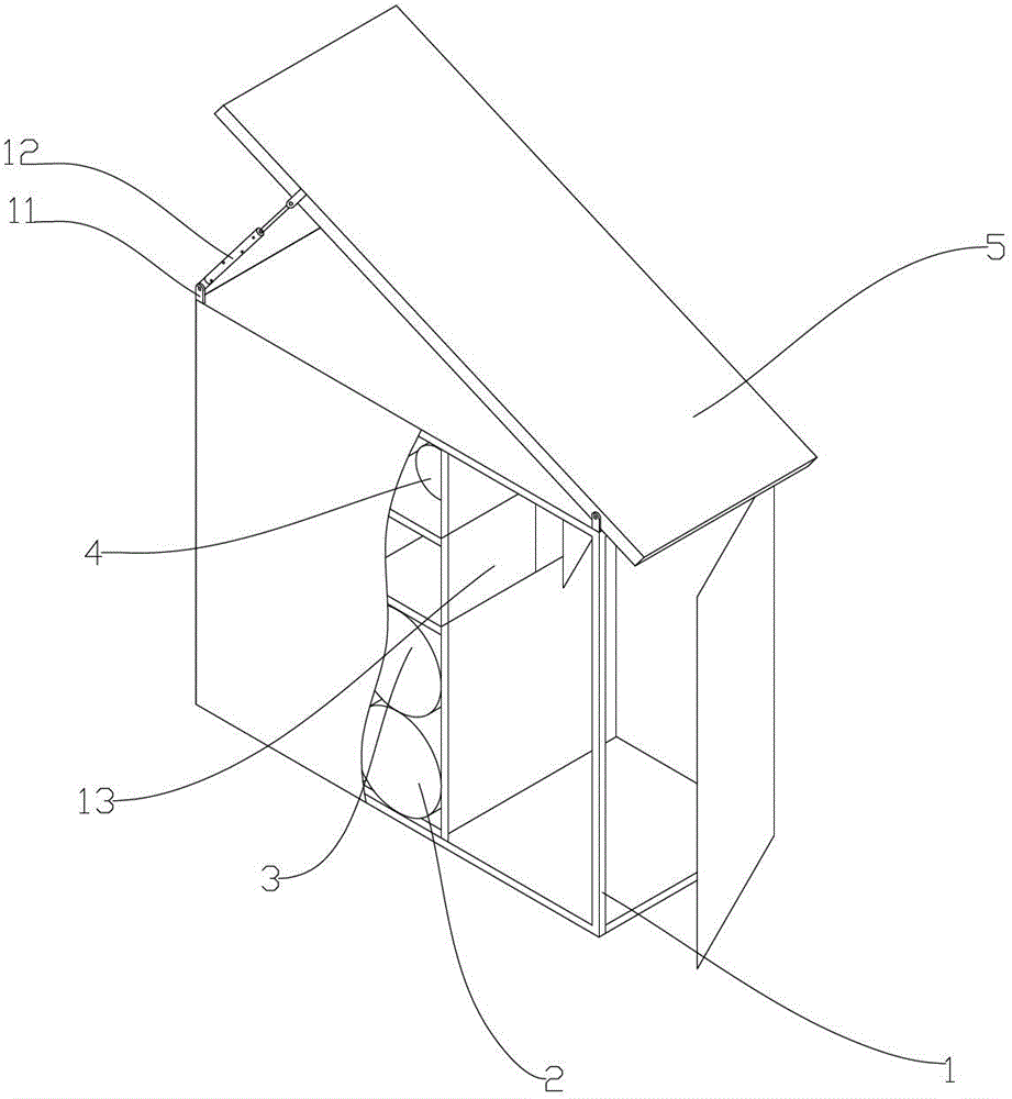
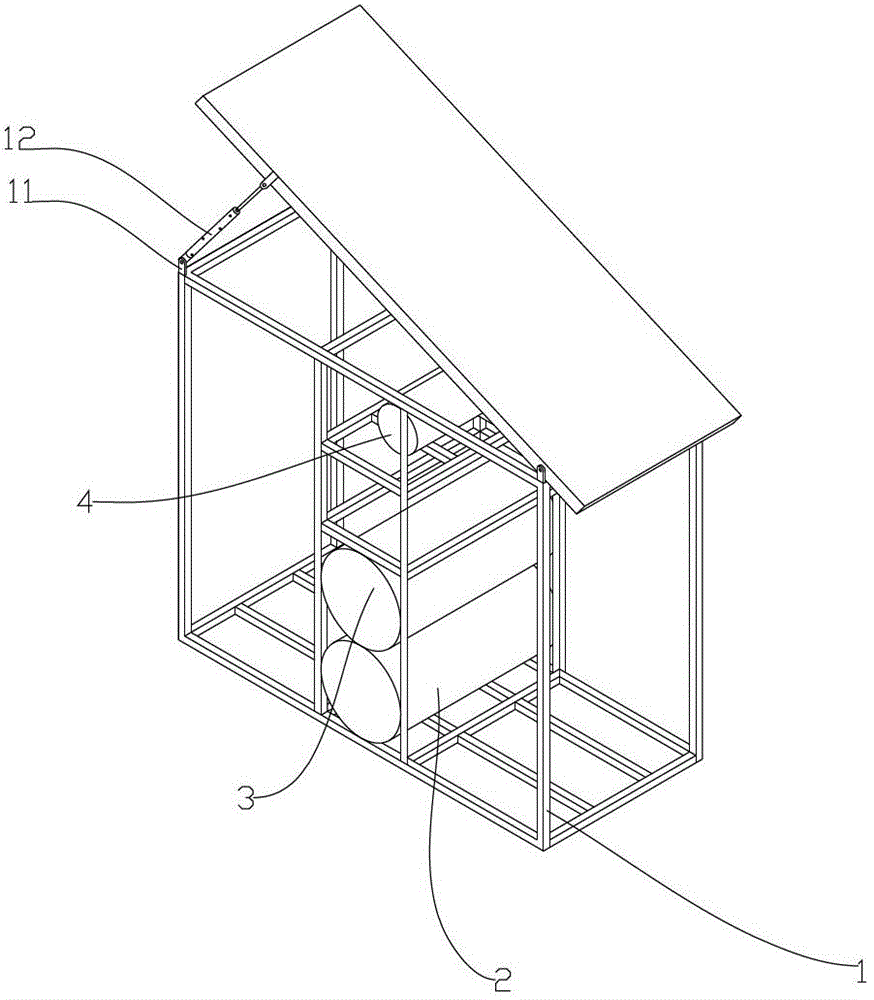
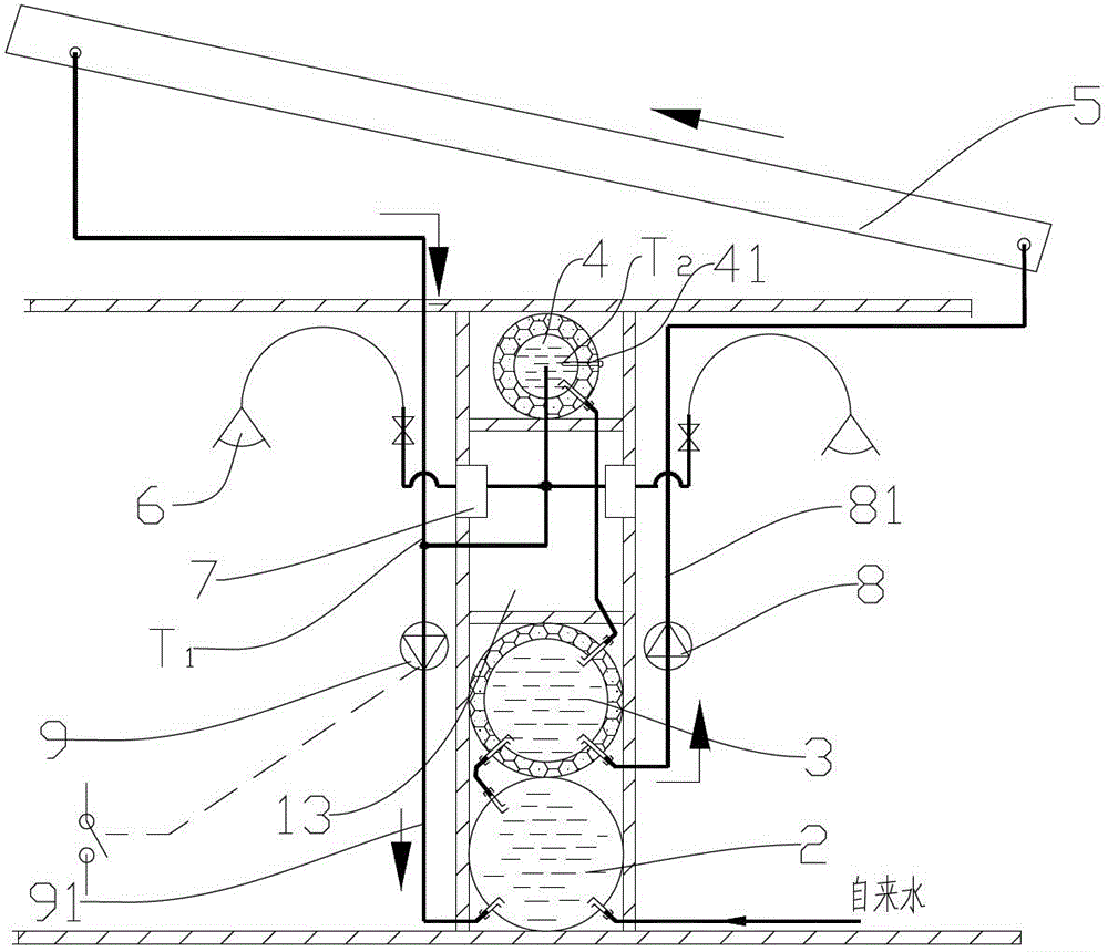
[0031] In this embodiment, the present invention includes a shower room composed of a metal frame 1 and a wall panel 14. A storage space is provided in the middle of the shower room, and the storage space separates the shower room into two Separate shower room. In order to achieve the purpose of maintaining water temperature and saving energy in the present invention, a constant temperature water tank 4 and a water pump are arranged in the upper part of the storage space; a buffer water tank 2 and a hot water storage tank 3 are arranged in the lower part of the storage space. The constant temperature water tank 4, the water pump, the buffer water tank 2 and the hot water storage tank 3 are connected by pipes; in this embodiment, the constant temperature water tank 4, the buffer water tank 2 and the hot water storage tank 3 are all horizontal bearing Pressurized water tank. The water pump includes a temperature regulating water pump 9 arranged on the connecting pipe 91 between ...

Embodiment 2

[0052] In this embodiment, a storage cabinet 13 is provided between the buffer water tank 2 and the hot water storage tank 3, so that clothes can be placed in it when taking a bath, without the need for an additional dedicated space.

[0053] The other parts of this embodiment are completely the same as the first embodiment.


PUM


Abstract

The invention discloses a movable solar shower system, which relates to a movable shower room. The movable solar shower system comprises a shower enclosure formed by a metal framework and wall panels. The movable solar shower system is characterized in that the middle position of the shower enclosure is provided with a storage space; the shower enclosure is divided into two independent shower rooms by the storage space; the storage space is provided with a constant-temperature water tank, water pumps, a buffer water tank and a thermal storage water tank; the top part of the shower enclosure is provided with a solar thermal collector; the water pumps comprise a thermoregulation water pump and a water circulating pump, wherein the thermoregulation water pump is arranged on a connecting pipeline arranged between the buffer water tank and the solar thermal collector, and the water circulating pump is arranged on a connecting pipeline between the thermal storage water tank and the solar thermal collector. The movable solar shower system disclosed by the invention is reasonable in structural arrangement and is convenient in movement. As the three water tanks are designed, a large amount of water can be stored. Shower room units not only can be independently used but also can be spliced together in actual use to form solar hot-water shower systems with different sizes.

Description

Technical field: [0001] The invention relates to a mobile solar shower system, which belongs to a mobile building, in particular to a movable shower room. Background technique: [0002] People living on construction sites need to take a shower every day. However, for cost saving considerations, most construction sites will not be equipped with hot showers and shower rooms. They can only shower with cold water in the shower room, and when the weather is cold, they will take some hot water to the shower room to take a shower. With the improvement of living standards and the popularization of civilized construction awareness, hot water shower rooms should be equipped on construction sites. However, there are several difficulties with this type of shower room. One: Most construction workers live in cheap sheds. The sheds will be demolished in two or three years. It is impossible to install expensive solar collectors on the sheds. The solar collector must be installed in a special...

Claims


Application Information

Patent Timeline
Patent Type & Authority Applications(China)
IPC IPC(8): E04H1/12A47K3/28F24J2/04F24J2/46
CPCY02E10/44
Inventor 罗刚段凯王莉芸张阳
Owner SHENZHEN INST OF BUILDING RES
Learn More