Electromagnetic control-based adjustable optical attenuator

A technology of dimming attenuation and electromagnetic control, applied in optics, instruments, optical components, etc., can solve the problems of elastic body mechanical fatigue, shorten device life, affect device performance, etc., and achieve low cost, high performance, and easy production Effect

Inactive Publication Date: 2012-10-24
NANJING UNIV OF POSTS & TELECOMM
View PDF10 Cites 7 Cited by
  • Summary
  • Abstract
  • Description
  • Claims
  • Application Information

AI Technical Summary

Problems solved by technology

Based on this kind of device structure, mechanical parts such as movable platform, positioning groove and elastic body are required, so the structure is complex, and the elastic body is prone to mechanical fatigue, which affects the performance of the device and shortens the life of the device.

Method used


Image

  • Electromagnetic control-based adjustable optical attenuator
  • Electromagnetic control-based adjustable optical attenuator
  • Electromagnetic control-based adjustable optical attenuator

Examples


Embodiment Construction

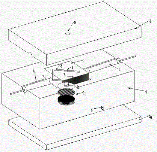
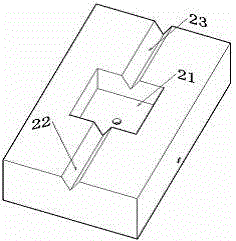
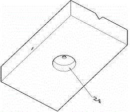
[0020] An electromagnetic control-based adjustable optical attenuator according to the present invention is characterized in that the device adopts a three-layer structure, the first layer is a cover plate 8, and a liquid injection hole (9) connected to the small hole 3 is left on the top plate; The second layer is the base waveguide layer 4, on which there is an outgoing fiber collimator 6 centered on the same horizontal line, a square waveguide 1, an electromagnetic drive device 11, a receiving fiber collimator 5, and a wiring hole 12 left on one side; The third layer is a flat plate substrate 20; the square waveguide 1 has a narrow gas-liquid cavity 2 along its diagonal direction, the upper end of the gas-liquid cavity is sealed, and a small hole 3 is left, and the lower end is sealed with the electromagnetic drive device 11 through a tube 10 connect. Electromagnetic driving device is left with the lid 15 of aperture, liquid chamber 17, permanent magnet sheet 14, electromag...


PUM


Abstract

The invention relates to an adjustable optical attenuator (VOA) in the field of photo-communication, which adopts a three-layer structure, wherein the first layer is a cover plate (8), and a liquid injecting hole (9) which corresponds to a small hole (3) of a gas-liquid chamber (2) is remained on the cover plate; the second layer is a waveguide layer (4) which comprises an emergent optical fiber collimator (6), a square waveguide (1), an electromagnetic driving device (11), a receiving optical fiber collimator (5) and a wire receiving hole (12); the third layer is a flat-plate base (20); a narrow gas-liquid chamber (2) which is along the diagonal direction of the square waveguide is arranged on the square waveguide (1), the upper end of the gas-liquid chamber is sealed, the small hole (3) is remained on the gas-liquid chamber, the lower end of the gas-liquid chamber is connected with the electromagnetic driving device (11) in a sealing way by a pipe (10), and one side of the square waveguide (1) is coated with a black light absorbing material (7); the cover plate, the waveguide layer and the base are connected with one another in the manner of auxiliary bonding by plasmas; and the light intensity coupling efficiency between the optical fiber collimators can be controlled by adjusting the height of index-matching fluid in the gas-liquid chamber (2), so that the optical controllable attenuation adjustment can be realized.

Description

technical field [0001] The patent of the invention relates to a novel variable optical attenuator structure and working principle, which belongs to the technical field of optical communication, photoelectric sensing and optical information processing devices. Background technique [0002] Variable Optical Attenuator (Variable Optical Attenuator, referred to as VOA) is an important optical fiber passive device in intelligent optical networks. It is widely used in channel gain balance and device protection of wavelength division multiplexing system (WDM / DWDM). The production methods of the adjustable optical attenuator include mechanical type, waveguide type, liquid crystal type, micromachine (MEMS) type and the like. Among them, waveguide-type and liquid crystal-type tunable optical attenuator technologies are still immature, and there are very few commercial products. The mechanical adjustable optical attenuator is the most mature, but its volume is large and its structur...

Claims


Application Information

Patent Timeline
IPC IPC(8): G02B26/02
Inventor 郭安金万静梁忠诚韦云亮张帅
Owner NANJING UNIV OF POSTS & TELECOMM
Why Eureka
Try Eureka