Cage type rotor permanent magnetic synchro motor starting device and control method

A permanent magnet synchronous motor, squirrel-cage rotor technology, applied in starting devices, single motor speed/torque control, etc., can solve the problems of long starting time, reduced starting torque, and high cost, and achieve high reliability and reduced Torque ripple, low cost effect

Inactive Publication Date: 2012-10-24
BEIJING UNIV OF TECH
View PDF5 Cites 4 Cited by
  • Summary
  • Abstract
  • Description
  • Claims
  • Application Information

AI Technical Summary

Problems solved by technology

[0003] The cage-type rotor permanent magnet synchronous motor can be directly started by connecting to the power frequency grid, but this method has the following problems: 1) The starting current is too large, which can reach more than ten times the rated current of the motor, which will seriously affect other electrical equipment on the small-capacity grid Normal operation will also cause serious heating of the motor windings, accelerate insulation aging, and affect the life of the motor; 2) The starting torque is uncontrollable, and it will inevitably cause serious mechanical shocks to the load driven by the motor when starting, and even damage the load
One is to use a transformer or a soft starter applied to an asynchronous motor for step-down starting, but the starting torque of this method will be greatly reduced and the starting time will be long, which cannot meet the needs of driving a large load; the other method is Use a general-purpose inverter to drive the motor, but the cost of the general-purpose inverter is relatively high due to the use of high-voltage full-control power electronic devices, especially as the power of the motor increases, the cost of the inverter will increase significantly, which is difficult for users to accept
The above problems seriously restrict the popularization and application of cage rotor permanent magnet synchronous motors

Method used


Image

  • Cage type rotor permanent magnetic synchro motor starting device and control method
  • Cage type rotor permanent magnetic synchro motor starting device and control method

Examples


Embodiment Construction

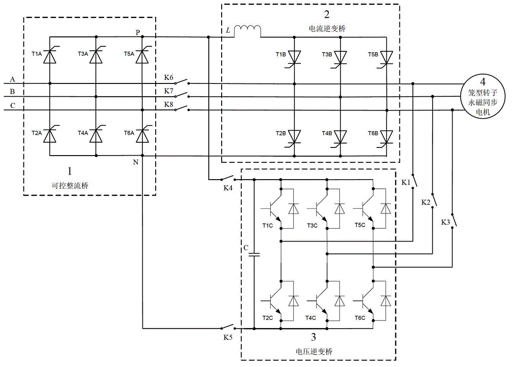
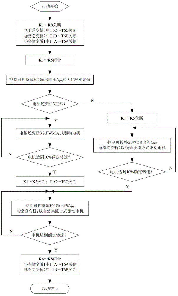
[0032] Combine below figure 1 , figure 2 The present invention is described further:

[0033] like figure 1 As shown, the present invention mainly includes a controllable rectifier bridge 1, a current inverter bridge 2, a voltage inverter bridge 3, a cage rotor permanent magnet synchronous motor 4 and switches K1-K8.

[0034] The input end of the controllable rectifier bridge 1 is connected to three-phase AC power sources A, B, and C. The input end of the current inverter bridge 2 is connected to the output end of the controllable rectifier bridge 1 , and its output end is connected to the input end of the cage rotor permanent magnet synchronous motor 4 . The input terminal of the voltage inverter bridge 3 is connected with the input terminal of the current inverter bridge 2 and the output terminal of the controllable rectifier bridge 1 through the switches K4 and K5, and its output terminal is connected with the current inverter bridge 2 through the switches K1, K2 and K3...


PUM


Abstract

The invention relates to a cage type rotor permanent magnetic synchro motor starting device and a control method, and belongs to the field of motor control. The starting device comprises a controllable rectification bridge (1), a current inversion bridge (2), a voltage inversion bridge (3), a cage type rotor permanent magnetic synchro motor (4) and switches K1-K8, wherein the input end of the controllable rectification bridge (1) is connected an A phase, a B phase and a C phase of three-phase alternating current; the input end of the current inversion bridge (2) is connected with the output end of the controllable rectification bridge (1), the output end of the current inversion bridge (2) is connected with the input end of the cage type rotor permanent magnetic synchro motor (4); and the input end of the voltage inversion bridge (3) is respectively connected with the input end of the current inversion bridge (2) and the output end of the controllable rectification bridge (1) through the switches K4 and K5, and the output end of the voltage inversion bridge (3) is respectively connected with the output end of the current inversion bridge (2) and the input end of the cage type rotor permanent magnetic synchro motor (4). The cage type rotor permanent magnetic synchro motor starting device provided by the invention can automatically realize switchover according to the running speed of the motor, and the cage type rotor permanent magnetic synchro motor starting device has the characteristics of low cost and large load-carrying capacity.

Description

technical field [0001] The invention belongs to the technical field of motor control, in particular to a starting device and a control method of a cage-type rotor permanent magnet synchronous motor. Background technique [0002] Cage rotor permanent magnet synchronous motor is a permanent magnet synchronous motor with squirrel-cage conductors on the rotor. Compared with traditional asynchronous motors and electrically excited synchronous motors, this motor has significant advantages such as high efficiency, high power factor, and high torque density. Therefore, it has great application prospects in industrial fields such as fans and water pumps. [0003] The cage-type rotor permanent magnet synchronous motor can be directly started by connecting to the power frequency grid, but this method has the following problems: 1) The starting current is too large, which can reach more than ten times the rated current of the motor, which will seriously affect other electrical equipment...

Claims


Application Information

Patent Timeline
Patent Type & Authority Applications(China)
IPC IPC(8): H02P6/08H02P6/21
Inventor 许家群阎宝光
Owner BEIJING UNIV OF TECH
Why Eureka
Try Eureka