
Method for preparing large-size optical fiber preform

An optical fiber preform, large-scale technology, applied in the field of optical fiber manufacturing, can solve the problems of complex manufacturing process, low deposition rate, and high geometric accuracy, and achieve the effects of flat and beautiful appearance, high deposition rate, and high deposition efficiency.

Active Publication Date: 2015-04-08
YANGTZE OPTICAL FIBRE & CABLE CO LTD
View PDF4 Cites 0 Cited by
  • Summary
  • Abstract
  • Description
  • Claims
  • Application Information

AI Technical Summary

Problems solved by technology

The casing method has the following disadvantages: large-sized casing requires high geometric accuracy, the manufacturing process is complicated, and material loss during casing processing leads to increased costs
However, the deposition rate is relatively slow compared to the OVD method
And using the VAD method alone, the quartz particles are adhered to the substrate and grow vertically downward, and the structure of the soot body is fragile. The size and weight of the soot body produced under the condition of no target rod are limited, and it is difficult to manufacture a large preform
[0006] In-tube PCVD and MCVD are suitable for preparing high-precision preforms with complex waveguide structures, but the deposition rate is low, and large-scale preforms cannot be prepared alone

Method used


Image

  • Method for preparing large-size optical fiber preform
  • Method for preparing large-size optical fiber preform
  • Method for preparing large-size optical fiber preform

Examples


Embodiment 1

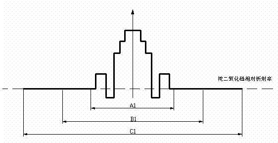
[0041] Embodiment 1: Large effective area and low water peak optical fiber preform.

[0042] According to the method of the invention, the quartz material containing Ge or F is deposited in the high-purity, low-hydroxyl quartz glass liner by PCVD. The hydroxyl content of the liner is less than 10ppb, and the waveguide structure in the core area is a segmented and stepped structure. Then the deposition tube was melted and shrunk at 1800° C. to 2100° C. to form a solid quartz core rod with a length of 1.2 m and a diameter of 25 mm.

[0043] Then use the VAD method to coat an appropriate amount of uniform quartz loose body on the outer surface of the quartz core rod and sinter it into a solid intermediate preform. The lower end of the target rod is suspended, and the upper end is clamped by the clamp 6 to rotate around the axis of the target rod at a speed of 5r / min, the lamp head of the VAD blowtorch does not move, the quartz rod moves vertically upwards, and the moving spee...

Embodiment 2

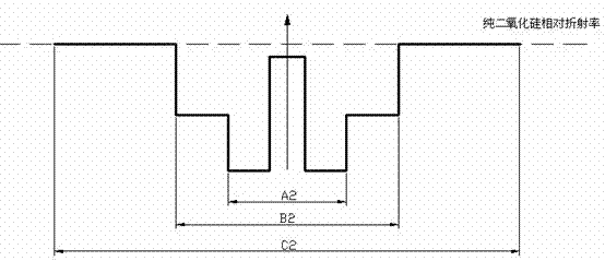
[0047] Embodiment 2: Radiation-resistant optical fiber preform.

[0048] According to the method of the invention, the MCVD method is used to deposit the F-containing core material in the high-purity, high-hydroxyl quartz glass liner. The hydroxyl content of the liner is higher than 1000ppm, and contains F, the relative refractive index difference of the liner is -0.36%, the relative refractive index difference of the inner cladding is the same as that of the liner, and the core waveguide structure is a step structure. The deposition tube was melted and shrunk at 1850° C. to 1950° C. into a solid quartz core rod, and the length of the quartz core rod was 1.5 m.

[0049] Then use the VAD method to coat an appropriate amount of uniform quartz loose body on the outer surface of the quartz rod. The lower end of the target rod is suspended in the air, and the upper end is clamped by the clamp 6 to rotate around the axis of the target rod at a speed of 120r / min. The lamp head of ...

Embodiment 3

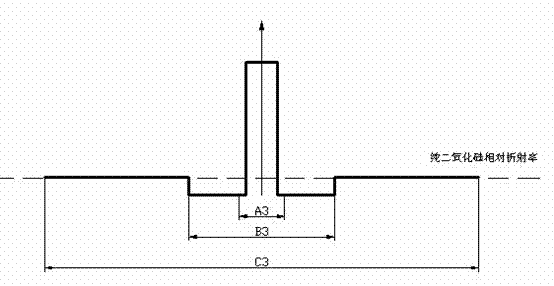
[0052] Embodiment 3: Single-mode optical fiber preform.

[0053] According to the method of the invention, the core material containing Ge is deposited in the high-purity, low-hydroxyl F-doped quartz glass liner by PCVD. The hydroxyl content of the liner is less than 10ppb, the relative refractive index difference is -0.1%, and the core waveguide structure is a stepped structure. Then, the deposition tube was melted and shrunk at 1800° C. to 2100° C. to form a solid quartz rod, and the length of the quartz rod was 1.1 m.

[0054] Then use the VAD method to coat an appropriate amount of uniform quartz loose body on the outer surface of the quartz rod and sinter it into a solid intermediate preform rod. The lower end of the target rod is suspended in the air, and the upper end is clamped by the clamp 6 to rotate around the axis of the target rod at a speed of 70r / min. , the lamp head of the VAD blowtorch does not move, and the quartz rod moves vertically upwards at a moving r...


PUM

PropertyMeasurementUnit
lengthaaaaaaaaaa
diameteraaaaaaaaaa
densityaaaaaaaaaa

Abstract

The invention relates to a method for preparing a large-size optical fiber preform, comprising the following steps: a mandril is prepared by the intra-tube chemical vapor deposition method, and the mandril comprises a fiber core layer, or a fiber core layer and part of inner cladding layer; the mandril is used as a target rod, a SiO2 loose body is prepared on the target rod by the VAD (Vapor Axial Deposition) method, and an inner cladding layer or part of inner cladding layer is formed; a primary optical fiber preform with uniform structure is obtained; and the primary optical fiber preform is used as the target rod, a SiO2 outer cladding layer is deposited on the primary optical fiber preform through the OVD (Outside Vapor Deposition) method, after the deposition is finished, and the primary optical fiber preform is sintered into a transparent optical fiber preform. The method is combined with the advantages of various deposition techniques, the disadvantages of the techniques are reasonably avoided, and the unification of high deposition rate, high performance and low cost is realized. The method is not only suitable for preparing a common single-mode optical fiber with a simple section, but is also suitable for preparing special optical fibers with precise and complicated sections.

Description

technical field [0001] The invention relates to a method for preparing an optical fiber preform by utilizing the cost advantage of an external deposition method and the precision advantage of an in-tube method, and belongs to the field of optical fiber manufacturing. Background technique [0002] Optical fiber preforms are used to prepare optical fibers for communication transmission media. Optical fiber manufacturing technology includes multiple links and processes, and preform rod manufacturing is one of the main processes. With the development of optical fiber preform technology, in order to improve the production efficiency of optical fibers, commercial preforms are currently moving towards the direction of making larger-sized optical fiber preforms. Larger-sized (diameter) preforms usually adopt the "two-step method" Manufacturing process, the first step is the manufacture of mandrel; the second step is outsourced manufacturing and rod forming. Among them, the manufac...

Claims


Application Information

Patent Timeline
Patent Type & Authority Patents(China)
IPC IPC(8): C03B37/018
CPCC03B37/01493C03B37/018
Inventor 曹蓓蓓倪先元渠驰罗杰
Owner YANGTZE OPTICAL FIBRE & CABLE CO LTD
Learn More