
Riser spiral-flow type falling-film evaporator for refrigerating air conditioner

A falling-film evaporator and falling-film evaporation technology, applied in evaporators/condensers, refrigerators, refrigeration components, etc., can solve problems such as dry evaporation and insufficient refrigerant flow, reduce liquid holding capacity and save power consumption , the effect of improving heat transfer performance

Inactive Publication Date: 2012-10-31
XI AN JIAOTONG UNIV
View PDF10 Cites 15 Cited by
  • Summary
  • Abstract
  • Description
  • Claims
  • Application Information

AI Technical Summary

Problems solved by technology

However, since the application of the horizontal tube falling film evaporator in the refrigeration system is still in the exploratory stage, there are still many technical problems to be solved, such as the structural form of the liquid distributor to achieve uniform liquid distribution and the optimal design of the geometric arrangement of the evaporator tubes , the problem of dry evaporation caused by insufficient refrigerant flow, the influence of the structure of the outer surface of the evaporation tube on heat transfer, and the influence of refrigerant airflow on liquid film disturbance, etc.

Method used


Image

  • Riser spiral-flow type falling-film evaporator for refrigerating air conditioner
  • Riser spiral-flow type falling-film evaporator for refrigerating air conditioner
  • Riser spiral-flow type falling-film evaporator for refrigerating air conditioner

Examples


Embodiment Construction

[0019] The present invention will be described in further detail below in conjunction with the accompanying drawings and specific embodiments.

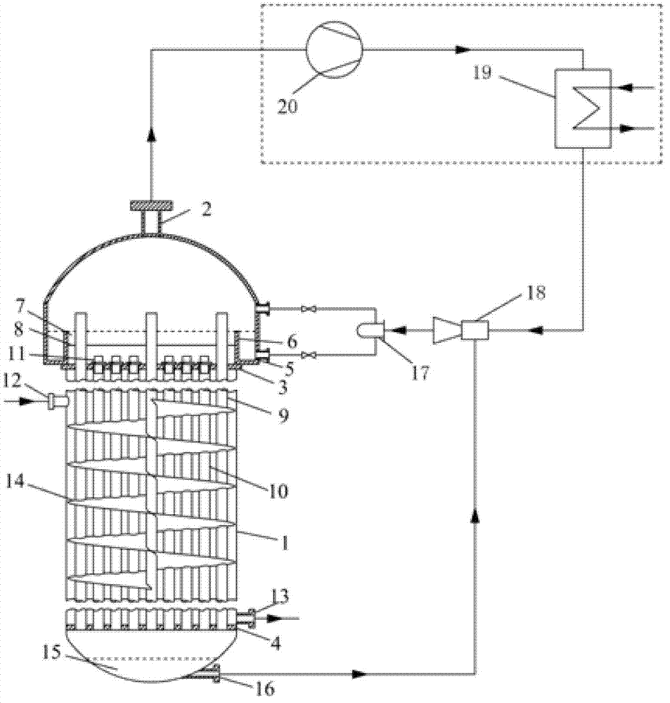
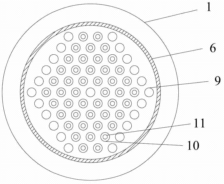
[0020] Such as figure 1 As shown, a standpipe swirl type falling film evaporator for refrigeration and air conditioning of the present invention comprises a shell 1, placed in the center of the shell 1 and a refrigerant vapor delivery tube bundle 9 arranged circumferentially along the inner wall of the shell 1. The falling film evaporation tube bundle 10 surrounded by the steam delivery tube bundle 9, the refrigerant steam delivery tube bundle 9 and the falling film evaporation tube bundle 10 are both vertically arranged in the shell 1, and there are helical folds arranged in a spiral along the vertical direction inside the shell 1 The flow plate 14, the refrigerant vapor delivery tube bank 9 and the falling film evaporation tube bank 10 pass through the through holes on the spiral baffle plate 14, and the upper tube plate 3 and the l...


PUM


Abstract

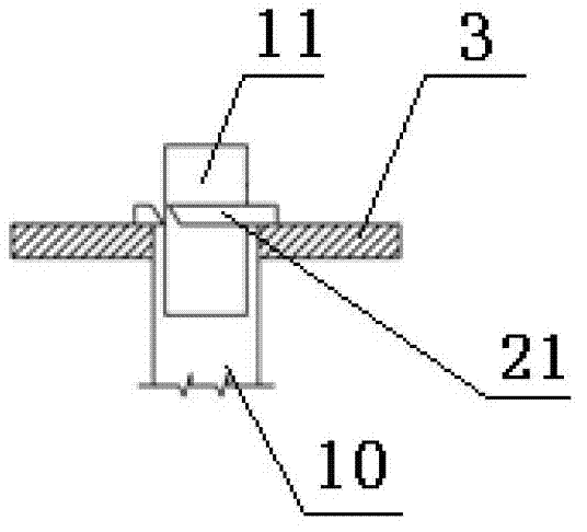
The invention discloses a riser spiral-flow type falling-film evaporator for a refrigerating air conditioner. The riser spiral-flow type falling-film evaporator comprises a shell, a refrigerant steam conveying pipe bundle, a falling-film evaporation pipe bundle, a damping hole plate and a spiral baffle plate, wherein the refrigerant steam conveying pipe bundle is arranged in the center in the shell and along the circumferential direction of the inner all of the shell, the falling-film evaporation pipe bundle is surrounded by the refrigerant steam conveying pipe bundle, the refrigerant steam conveying pipe bundle and the falling-film evaporation pipe bundle are both vertically arranged inside the shell, the upper part of an inlet of the falling-film evaporation pipe bundle is horizontally provided with the damping hole plate, the spiral baffle plate is fixed inside the shell and spirally arranged along a vertical direction, and is provided with through holes allowing the refrigerant steam conveying pipe bundle and the falling-film evaporation pipe bundle to pass through, an ejector is arranged between a refrigerant outlet pipe and a refrigerant inlet pipe, the inlet of the falling-film evaporation pipe bundle is provided with a flow guiding nozzle which has an outer diameter smaller than the inner diameter of the falling-film evaporation pipe bundle and is sealed at two ends, and the flow guiding nozzle is provided with a circular ring with three chutes formed along a circumferential direction uniformly. The riser spiral-flow type falling-film evaporator has the characteristics of small heat transfer temperature difference, high heat transfer coefficient, large evaporative power of unit area capable of preventing dry evaporation, low manufacture cost, less liquid holdup, small floor area and high safety.

Description

technical field [0001] The invention belongs to the technical field of refrigeration and air conditioning, and relates to a vertical tube falling film evaporator, in particular to a vertical tube swirl type falling film evaporator for refrigeration and air conditioning. Background technique [0002] With the rapid development of my country's national economy, the demand for large and medium-sized refrigeration and air-conditioning devices is increasing day by day. As a large and medium-sized refrigeration and air-conditioning device, the technical level of cold (hot) water units has been continuously improved, and the variety and output have continued to increase. In water chillers, such as centrifugal and screw chillers, the evaporator is a key heat exchange equipment in the system; the previous types of evaporators are mainly flooded evaporators and dry evaporators, of which flooded There are many applications. In recent years, under the background of the development nee...

Claims


Application Information

Patent Timeline
IPC IPC(8): F25B39/02F28F9/24F28F13/00
Inventor 鱼剑琳周媛媛王骁马明厉彦忠
Owner XI AN JIAOTONG UNIV
Learn More