
Clock circuit capable of realizing stable duty ratio and phase calibration

A phase calibration and clock circuit technology, applied in the direction of electrical components, single output arrangement, pulse processing, etc., can solve the problems that affect the correction accuracy of the correction circuit, increase system power consumption, limit operating frequency, etc., to improve accuracy and reduce design Difficulty, the effect of ensuring accuracy

Active Publication Date: 2012-10-31
BEIJING MXTRONICS CORP +1
View PDF5 Cites 24 Cited by
  • Summary
  • Abstract
  • Description
  • Claims
  • Application Information

AI Technical Summary

Problems solved by technology

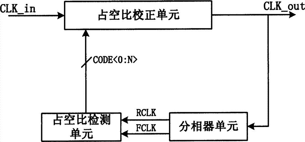
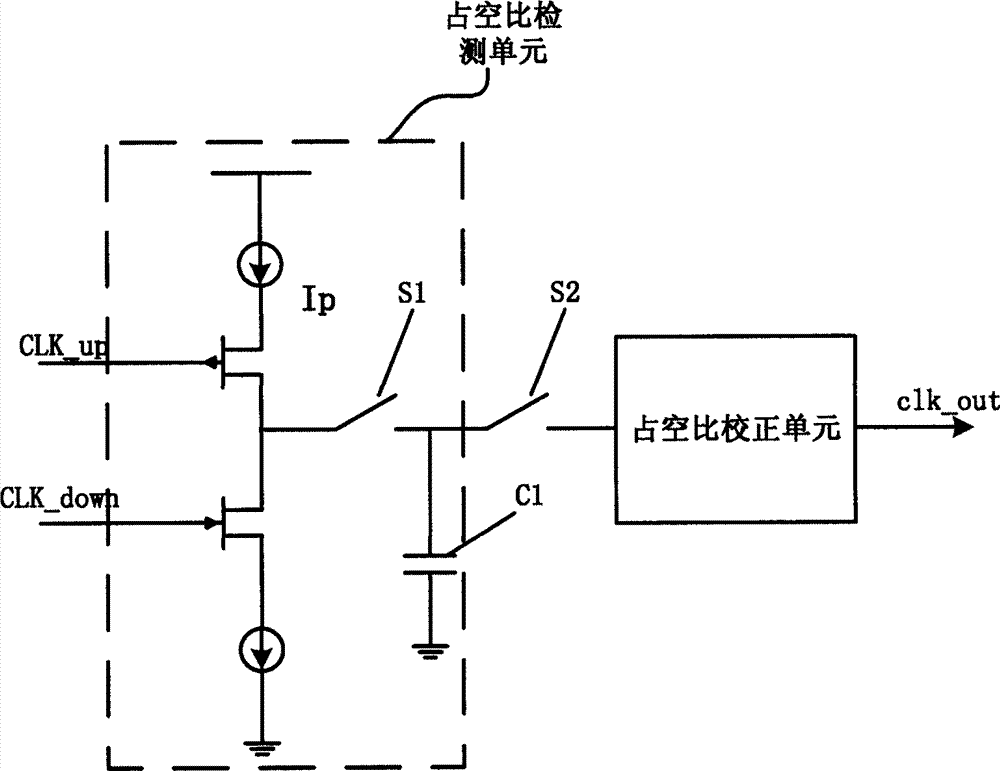
[0006] The advantage of the analog method is that it can achieve higher calibration accuracy. The disadvantage is that the design is more difficult. In addition, it can be divided into different forms according to the duty ratio detection method. At present, the commonly used ones are the use of frequency-voltage converter (FVC) and the use of charge In the form of a pump, the method of using frequency-voltage conversion requires the use of switched capacitors, which reduces the calibration accuracy due to charge leakage and other reasons, and also limits the operating frequency; and the use of charge pumps for calibration at high clock frequencies greatly increases The power consumption of the system is reduced, and the matching degree of the charge and discharge current of the charge pump also greatly affects the correction accuracy of the correction circuit.

Method used


Image

  • Clock circuit capable of realizing stable duty ratio and phase calibration
  • Clock circuit capable of realizing stable duty ratio and phase calibration
  • Clock circuit capable of realizing stable duty ratio and phase calibration

Examples


Embodiment Construction

[0031] The present invention will be further introduced below in conjunction with the accompanying drawings.

[0032] Such as image 3 Shown is a schematic structural diagram of the present invention, including: a duty cycle correction module, a phase adjustment module and a clock distribution network.

[0033] The duty ratio stabilization module includes an input stage amplifier, a buffer amplifier, and a common-mode feedback amplifier. The input stage amplifier is a differential-single-ended amplifier, which can convert the differential signal into a single-ended square wave signal, and then enter the buffer amplifier for buffering and outputting a square wave signal with a fixed duty cycle, and the output signal will also be used as a feedback signal Input to the common-mode feedback amplifier, which is composed of an average level extraction circuit and a feedback amplifier, wherein the average level extraction circuit integrates the input signal, and outputs the integrat...


PUM


Abstract

The invention discloses a clock circuit capable of realizing a stable duty ratio and phase calibration, which is used for adjusting the duty ratio and the phase of a clock signal. The clock circuit comprises a clock distribution network used for carrying out buffer output on the clock signal, a duty ratio correction module and a phase calibration module, wherein the duty ratio correction module is used for converting an input differential signal into a square signal with a fixed duty ratio and then outputting the square signal to the phase adjustment module; and the phase adjustment module is used for adjusting the phase of the input square signal by utilizing an in-phase clock signal and an antiphase clock signal which are fed back by the clock distribution network and generating and inputting a clock signal to the clock distribution network. By adopting the clock circuit, the purposes of stable duty ratio and phase calibration of the output clock signal are achieved.

Description

technical field [0001] The invention belongs to the field of integrated circuit clock system design and relates to a clock circuit with stable duty cycle and phase calibration. Background technique [0002] With the continuous shrinking of the integrated circuit process size and the continuous improvement of the integration level, the working speed of the chip has been continuously improved and has reached the order of GHz. Since the synchronous operation is realized through the clock signal, the timing requirements for the clock become more stringent. For the clock system For the system, the duty cycle and time domain uncertainty are two very important indicators. For a system that uses double-edge, multi-channel clock interleaving, the clock signal has a fixed 50% duty cycle and multi-channel interleaving. It is a necessary condition for the high-performance operation of the system that the clock signal has a fixed phase difference. [0003] For a high-speed clock system,...

Claims


Application Information

Patent Timeline
Patent Type & Authority Applications(China)
IPC IPC(8): H03K5/13H03K5/135H03K5/14
Inventor 何斌王宗民张铁良蔡伟杨松虞坚郭晨光郭永恒
Owner BEIJING MXTRONICS CORP
Learn More