Multifunctional foam cutting machine

A cutting machine, multi-functional technology, applied in metal processing and other directions, can solve the problems of unsuitable production and application of small enterprises, low manual cutting efficiency, poor surface roughness, etc., to facilitate promotion and use, and save calculation and operation time. , Improve the effect of surface accuracy

Inactive Publication Date: 2012-11-07
CHUZHOU JINNUO INDAL
View PDF5 Cites 0 Cited by
  • Summary
  • Abstract
  • Description
  • Claims
  • Application Information

AI Technical Summary

Problems solved by technology

[0002] The existing methods of processing and manufacturing foam patterns in the lost foam casting industry generally use mold forming, numerical control cutting, manual cutting and cutting table cutting. Mold forming needs to make foam pattern molds first, and then form them. This method is costly and requires preparation. The cycle is long, which is suitable for the production of large batches of products; CNC cutting requires the purchase of CNC cutting machines and some auxiliary equipment. This method requires high investment in equipment and is not suitable for the production and application of small enterprises; manual cutting has low efficiency and poor surface roughness. The size error is large, and it takes up human resources; the cutting table is commonly used to cut the foam pattern, but the ordinary cutting table can only cut horizontally or vertically. Manual cutting, this method has disadvantages such as low efficiency, inaccurate size, and rough surface. If there is a cutting table that can quickly adjust the angle, high precision, and low cost, it will greatly improve production efficiency and product quality.

Method used


Image

  • Multifunctional foam cutting machine
  • Multifunctional foam cutting machine
  • Multifunctional foam cutting machine

Examples


Embodiment

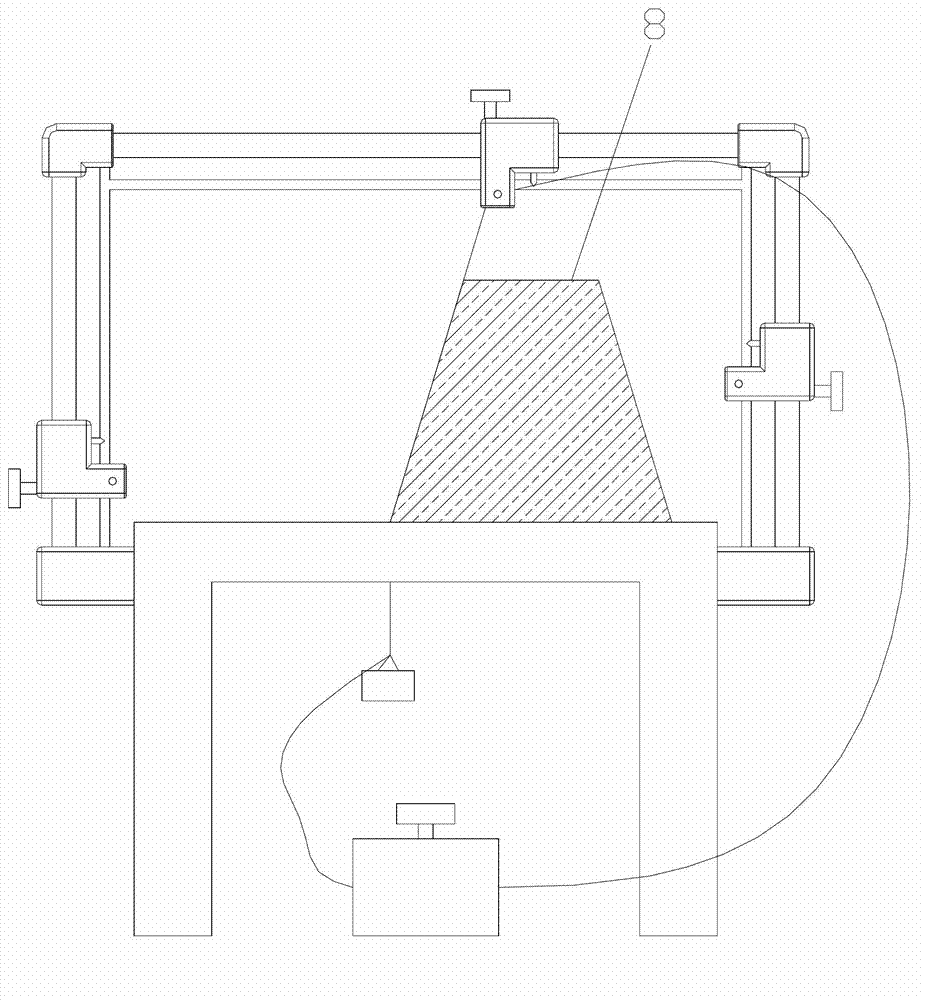
[0018] There is a foam shape that needs to be cut into an isosceles trapezoid. Now use the vertical wire of this cutting machine to cut it. The steps are as follows:

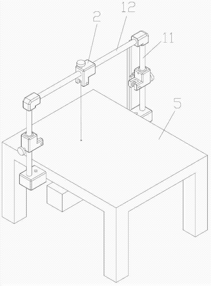
[0019] a. Assemble the device to a ready-to-use state, and connect to the power supply;

[0020] b. Cut into square materials according to the maximum size of pattern 8;

[0021] c. Calculate the angle between the hypotenuse and the horizontal plane;

[0022] d. Adjust the vertical adjustment mechanism 2 so that its pointer points to the angle value calculated in the previous step;

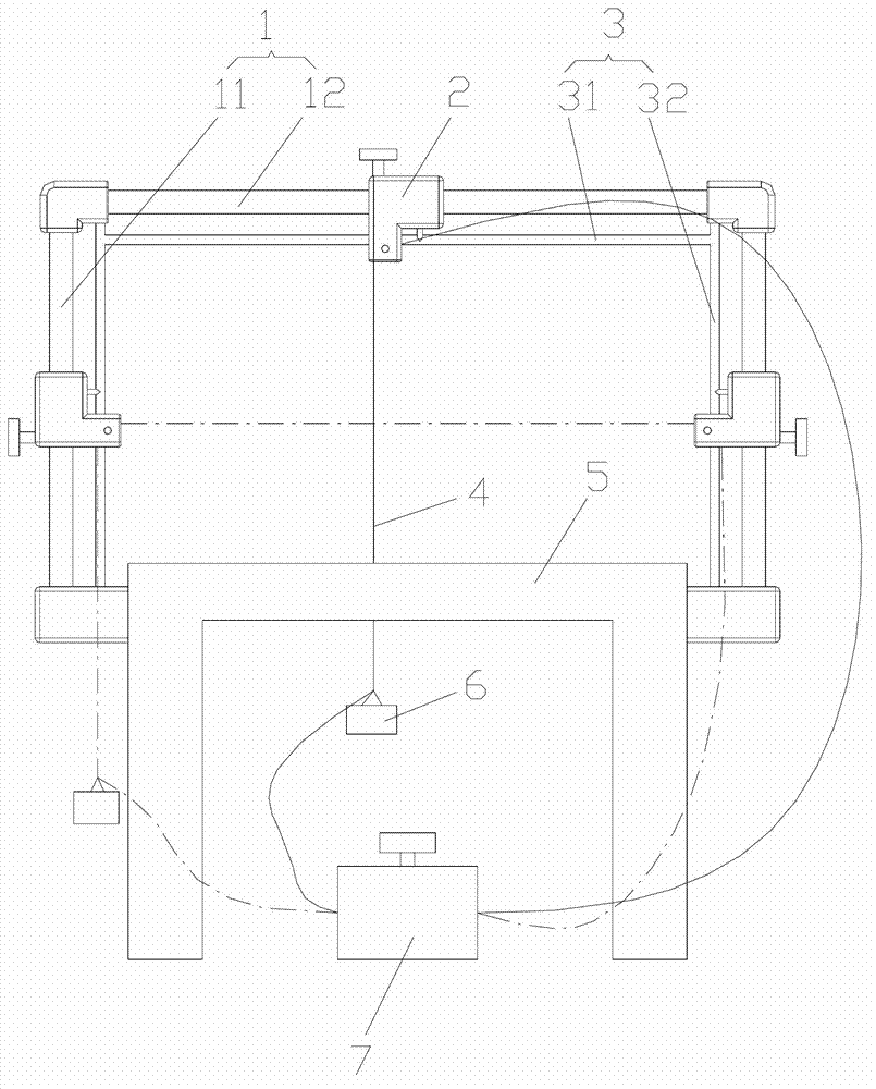
[0023] e. Turn on the power supply and adjust the power regulator 7 to the required voltage position;

[0024] f. When the heating wire 4 is heated and can be cut, align the lower end of the pattern 8 with the lower end of the heating wire 4, and move the pattern 8 at a constant speed. At this time, the cutting of a hypotenuse of the isosceles trapezoid is completed;

[0025] g. According to the previous step, cut the slope on th...


PUM


Abstract

The invention discloses a multifunctional foam cutting machine, relating to the technical field of foam cutting. The multifunctional foam cutting machine comprises a working table and further comprises a heating wire, wherein a portal frame composed of a polish rod is fixed on the two sides of the working table; an adjusting mechanism is arranged on the polish rod; two ends of the heating wire are respectively connected with two output electrodes of a power voltage adjuster; and the heating wire passes through a pulley of the adjusting mechanism and is tied with a counterweight. According to the multifunctional foam cutting machine, a linear bearing is provided with the polish rod, so that the motion precision of the heating wire is improved, that is the manufacturing precision of foam patterns is improved; a display mechanism is provided, so that the size can be more quickly and accurately adjusted and the working time is saved; the angular cutting operation can be carried out, the materials, time and efforts for manufacturing copy bodies are saved, the calculating and operating time for scribing is also saved and the error rate is reduced; and meanwhile, the original manual cutting way is changed, the cut flatness of the patterns is improved and the surface precision of the patterns is also improved. The multifunctional foam cutting machine is simple in structure, convenient to operate, low in manufacturing cost and convenient to popularize and use.

Description

Technical field: [0001] The invention relates to the technical field of foam cutting and processing, in particular to a multifunctional foam cutting machine, which belongs to the mechanical processing industry. Background technique: [0002] The existing methods of processing and manufacturing foam patterns in the lost foam casting industry generally use mold forming, numerical control cutting, manual cutting and cutting table cutting. Mold forming needs to make foam pattern molds first, and then form them. This method is costly and requires preparation. The cycle is long, which is suitable for the production of large batches of products; CNC cutting requires the purchase of CNC cutting machines and some auxiliary equipment. This method requires high investment in equipment and is not suitable for the production and application of small enterprises; manual cutting has low efficiency and poor surface roughness. The size error is large, and it takes up human resources; the cut...

Claims


Application Information

Patent Timeline
IPC IPC(8): B26F3/12B26D7/26B26D7/28
Inventor 马正松张玉胜赵玉林
Owner CHUZHOU JINNUO INDAL
Why Eureka
Try Eureka