

Nonlinear inductor loss measuring method based on direct current bias
A technology of DC bias and inductance loss, which is applied in the direction of measuring devices, measuring electrical variables, measuring resistance/reactance/impedance, etc., and can solve problems such as different losses, long solution process, and errors
- Summary
- Abstract
- Description
- Claims
- Application Information
AI Technical Summary
Problems solved by technology
Method used
Image

Examples
Embodiment Construction
[0060] The present invention will be further described below with reference to accompanying drawing:
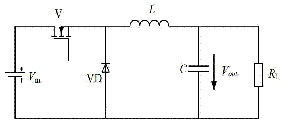
[0061] In this embodiment, the loss of the inductance in the Buck circuit is measured, and the Buck circuit is as figure 1 As shown, the input voltage of the circuit is V in =5V, the output voltage is V out =1.3V, the working frequency is f=8MHz, the average current after the circuit enters the steady state is I dc =13A.
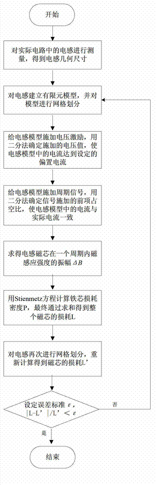
[0062] refer to image 3 , the present invention is as follows to the loss test procedure of inductance in Buck circuit:
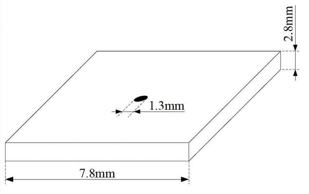
[0063] Step 1, use a micrometer to measure the size of the measured inductance to obtain the geometric parameters of the inductance.
[0064] The inductance L in the test circuit is a low temperature co-fired ceramic LTCC inductance, which is a cube, such as figure 2 As shown, the micrometer measures the size of the inductor. The side length is 7.8mm and the thickness is 2.8mm. The through hole in the center of the inductor repre...
PUM
 Abstract
Description
Claims
Application Information