Axial feeding type spiral conveying device and method

A technology of screw conveying device and screw conveyor, which is applied in the field of axial feed screw conveying device, can solve the problems of large gap between the inner diameter of the blade and the cylinder, easy disconnection of the welding position of the rotating shaft, and influence on the efficiency of the screw conveying, etc. Small power, convenient power transmission, and the effect of reducing oil resource consumption

Inactive Publication Date: 2014-05-07
SOUTH CHINA UNIV OF TECH
View PDF5 Cites 0 Cited by
  • Summary
  • Abstract
  • Description
  • Claims
  • Application Information

AI Technical Summary

Problems solved by technology

Since this type of screw conveyor does not adopt axial feeding, it cannot pass bulk granular materials in the hollow to realize continuous conveying of multiple sets in series.
[0004] With the development of screw conveyors in the direction of long distance, high power, high speed, and high performance, many problems must be involved in the long-distance closed transportation of bulk granular materials. For example, the screw conveyors commonly used in the market currently have The problems include: ①The length of the working member, that is, the screw blade shaft, is limited by the processing capacity of the equipment and the screw precision requirements; ②The long-distance transportation of the screw conveyor is limited by terrain, ground objects, etc., and the conveying direction cannot be changed; ③The length of the screw conveyor is limited. The axial thrust is very large during long-distance conveying, which requires a high-power drive motor. The impact of the material will also accelerate the wear of the screw blade shaft, and in severe cases, the blade of the screw shaft will be torn; ④The axial thrust of the screw conveyor is very Large and cause serious wear of the screw, so that the gap between the blade and the inner diameter of the cylinder is too large, which affects the efficiency of the screw conveying, and the welding position of the rotating shaft is easy to disconnect

Method used


Image

  • Axial feeding type spiral conveying device and method
  • Axial feeding type spiral conveying device and method

Examples


Embodiment Construction

[0024] The present invention will be described in further detail below in conjunction with the accompanying drawings, but the embodiments of the present invention are not limited thereto.

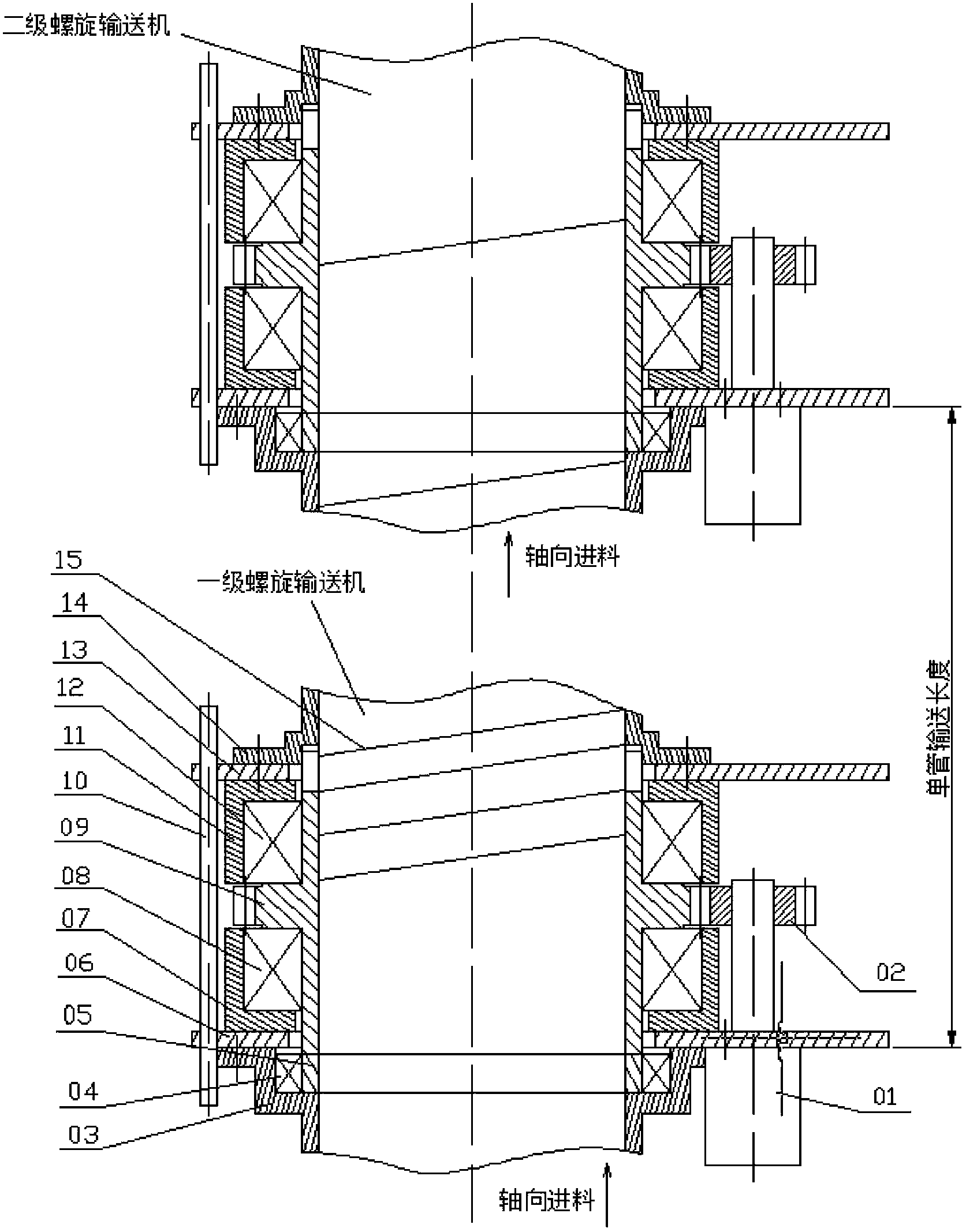
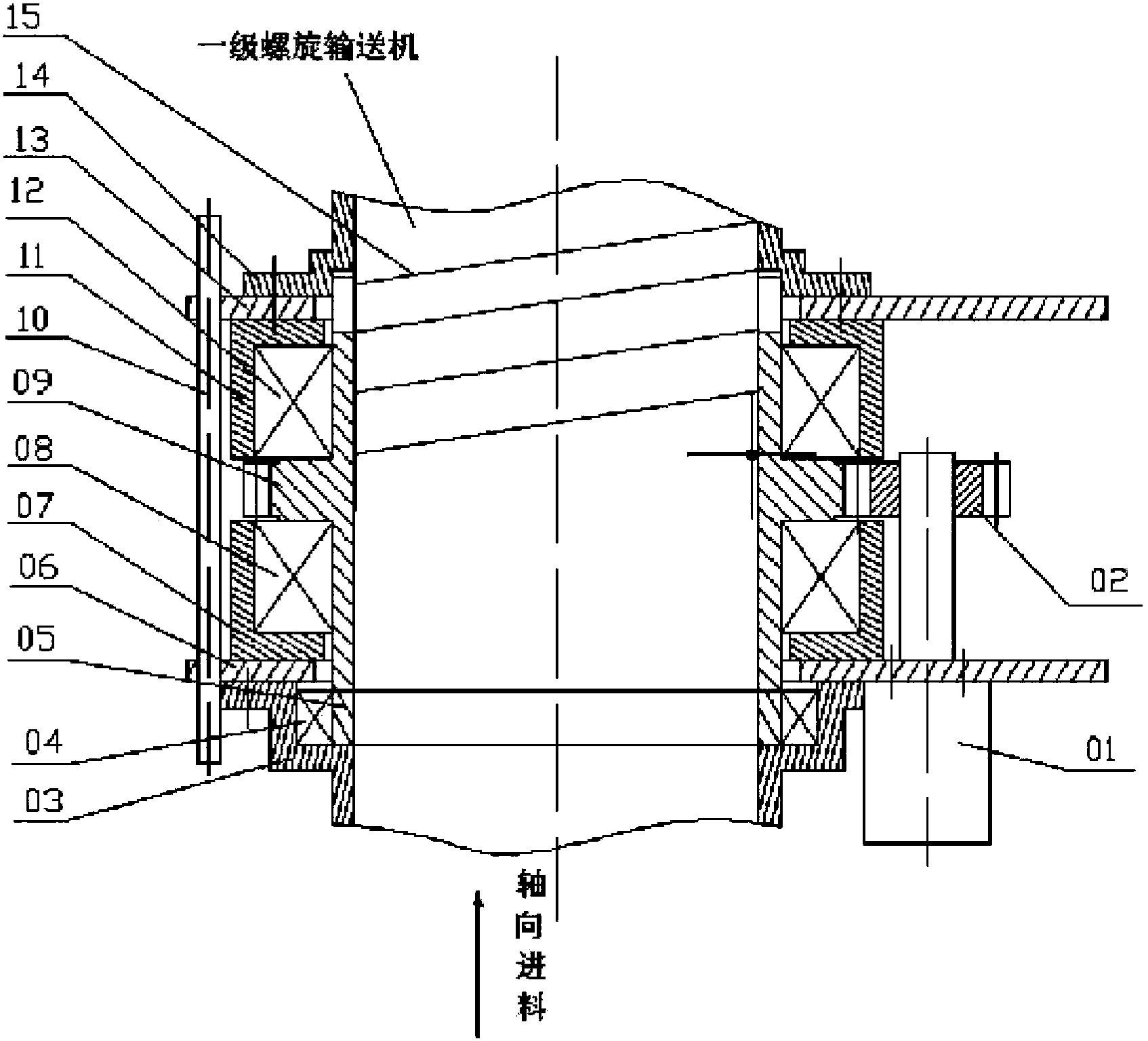
[0025] Such as figure 1 , 2 As shown, the axial feed screw conveyor is composed of multi-stage axial feed screw conveyors; each stage of axial feed screw conveyor includes a motor 01, a power input end 02, and a first spiral casing 03 , radial bearing 04, bearing bushing 05, first support plate 06, first thrust bearing seat 07, first thrust bearing 08, hollow rotating shaft 09, connecting rod 10, second thrust bearing seat 11, second thrust bearing 12. The second support plate 13, the second helical sleeve 14 and the helical blade shaft 15; the helical blade shaft 15 is a general helical blade for axial transmission, and the two ends of the helical blade are fixed on the hollow circular sleeve; the hollow Both ends of the rotating shaft 09 are respectively connected with the first spiral ...


PUM


Abstract

The invention discloses an axial feeding type spiral conveying device and method. The axial feeding type spiral conveying device comprises multirole stages of axial feeding type spiral conveyors; the axial blade shaft of each stage of axial feeding type spiral conveyor is an axial spiral blade; two ends of the axial blade are fixed on hollow round sleeves; two ends of a hollow rotating shaft are connected with a first spiral sleeve and a second spiral sleeve respectively; the hollow rotating shaft, the first spiral sleeve and the second spiral sleeve form a coaxial hollow structure; the axial blade shaft is arranged in the coaxial hollow structure; the round sleeves on two ends of the axial blade shafts are connected with the two ends of the hollow rotating shaft respectively; a motor is connected with a power input end through a transmission shaft; and the power input end is movably connected with the hollow rotating shaft. The front-stage spiral conveyor is connected with the rear-stage spiral conveyor by a connection rod, and the front-stage spiral conveyor and the rear-stage spiral conveyor adopt the axial feeding form so that the long-distance closed type conveying of bulk particle materials is realized. The axial feeding type spiral conveying device can be used for conveying a large amount of bulk materials by long distance.

Description

technical field [0001] The invention relates to a screw conveyor, in particular to an axial feeding screw conveyor device and method. Background technique [0002] Screw conveyor is a commonly used continuous conveying machine without flexible traction components, and it is one of the important mechanical equipment that is indispensable for modern production and logistics transportation. Its wide application has important practical significance for alleviating heavy physical labor, improving labor productivity, and realizing the mechanization and automation of material conveying process. Screw conveyors have been widely used in various sectors of the national economy and have been used in various industries. In metallurgy, mining, power, building materials, docks and other heavy industries and transportation departments, it is mainly used to transport bulk bulk materials, such as coal, ore, grain, sand, chemical fertilizers, etc.; in the machinery manufacturing department, ...

Claims


Application Information

Patent Timeline
Patent Type & Authority Patents(China)
IPC IPC(8): B65G33/14B65G33/34
Inventor 吴上生林晓蒙黄泽星胡子高
Owner SOUTH CHINA UNIV OF TECH
Why Eureka
Try Eureka