
CO2 drive oil-gas-water separate well injecting oil reservoir mixing drive development method

An oil-gas-water mixed flooding technology, applied in the direction of production fluid, earthwork drilling, wellbore/well components, etc., can solve problems such as low recovery, corrosion, poor formation capacity maintenance, etc., to expand the swept volume, apply The effect of broad prospects and good guidance

Active Publication Date: 2012-11-14
CHINA PETROLEUM & CHEM CORP +1
View PDF3 Cites 23 Cited by
  • Summary
  • Abstract
  • Description
  • Claims
  • Application Information

AI Technical Summary

Problems solved by technology

The characteristics of these four methods are as follows: continuous gas injection often has a small gas sweep coefficient, especially for reservoirs with severe heterogeneity, the breakthrough is very early, and the range of enhanced recovery is small; water-gas alternate injection can increase the efficiency of injected gas. Sweep factor, but causes water shielding and CO 2 Bypass oil, increased water injection pressure, and serious corrosion problems; the huff and puff oil recovery method is generally suitable for small-scale production methods, and its recovery rate is low; the periodic injection method of CO 2 The breakthrough speed is relatively slow, but the pressure drops rapidly during the injection stop period, and the formation capacity is poor

Method used


Image

  • CO2 drive oil-gas-water separate well injecting oil reservoir mixing drive development method
  • CO2 drive oil-gas-water separate well injecting oil reservoir mixing drive development method
  • CO2 drive oil-gas-water separate well injecting oil reservoir mixing drive development method

Examples


Embodiment Construction

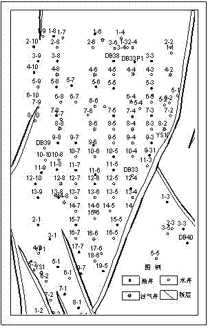
[0020] The following is combined with the accompanying drawings to illustrate the CO injection in an oil field 2 The scheme in oil flooding reservoir engineering is taken as an example to illustrate the implementation process and related effects of the present invention.

[0021] Step 1: According to the geological research data of the oilfield, monitoring data and production dynamic data of oil and water wells, determine that the production well pattern of the oil reservoir is a column well pattern, the well spacing is 500m*180m, and the development strata are Qing 1 and Qing 2 V .

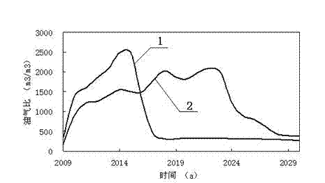
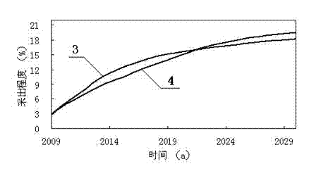
[0022] The second step: on the basis of the gas drive in the whole area, use the numerical simulation calculation of the whole process to carry out the simulation calculation. According to the calculation results, the gas breakthrough time and gas channeling time of the production wells were counted; and the production wells were further sorted according to the time when the oil-gas ratio reache...


PUM


Abstract

The invention provides a CO2 drive oil-gas-water separate well injecting oil reservoir mixing drive development method, and belongs to the field for improving recovery ratio of an oil reservoir. The method comprises the following steps of: firstly, determining a development well pattern, well spacing and a development layer system of the oil reservoir; then, utilizing an overall process numerical simulation technique to determine advantage seepage direction and sweep efficiency of injection gas, designing an injection well in the advantage seepage direction of the injection gas as a water injection well, designing other injection wells as a gas injection well, forming water-gas mixed drive of partial water injected to well and partial gas injected into well; and finally determining the injection parameter of an injection production well and the development index forecast of a whole region. The method can form a water barrier in a gas channeling direction, thereby effectively controlling gas channeling, enlarging swept volume of the injected gas, and improving recovery efficiency; and the method provided by the invention has excellent guiding function on the gas injection drive oil well pattern, well type and injection and production parameter of a developed block and an undeveloped block, and the application prospect is wide.

Description

technical field [0001] The invention belongs to the field of enhanced oil recovery, in particular to a CO 2 A mixed flooding development method for injecting oil, gas and water into different wells. Background technique [0002] With the increasing impact of the greenhouse effect on the world's climate, CO 2 It has become one of the focuses of people's most attention. CO storage 2 It is one of the effective ways to avoid climate change. Geological storage is generally considered to be the mainstream storage method in the future, and the geological structure with the most storage potential is the oil or gas field that is being exploited or has been depleted. [0003] Most oilfield reservoirs in my country belong to continental deposits with serious heterogeneity and relatively high viscosity of crude oil. The water cut of this type of reservoir rises rapidly, and even with enhanced injection and production measures, the water flooding recovery rate is still very low. In ...

Claims


Application Information

Patent Timeline
Patent Type & Authority Applications(China)
IPC IPC(8): E21B43/16E21B43/20
Inventor 计秉玉赵淑霞何应付廖海婴吕成远周银邦王强
Owner CHINA PETROLEUM & CHEM CORP
Learn More