
Crankshaft used for high-speed warp knitting machine

A high-speed warp knitting machine and crankshaft technology, which is applied in the direction of crankshaft, warp knitting, textiles and papermaking, etc., can solve the problem that the production speed of four-bar warp knitting machine is difficult to increase, and affects the normal use of the machine for a long time, design and balance. Complicated problems, to achieve the effect of stable and reliable weaving performance, simple and effective implementation, and improved production efficiency

Active Publication Date: 2014-12-10
ZHEJIANG YUEJIAN INTELLIGENT EQUIP CO LTD
View PDF6 Cites 0 Cited by
  • Summary
  • Abstract
  • Description
  • Claims
  • Application Information

AI Technical Summary

Problems solved by technology

The disadvantage is that when the movement is more complex, more components are required, and the design and balance problems are more complicated; there are gaps in the contact surfaces of each kinematic pair, and the more components, the greater the cumulative error of the mechanism
Due to the lack of processing, assembly and maintenance of machine parts, which affects the normal use of the machine for a long time, it is difficult to increase the production speed of the existing four-bar warp knitting machine, and the production efficiency is not high.

Method used


Image

  • Crankshaft used for high-speed warp knitting machine
  • Crankshaft used for high-speed warp knitting machine
  • Crankshaft used for high-speed warp knitting machine

Examples


Embodiment 1

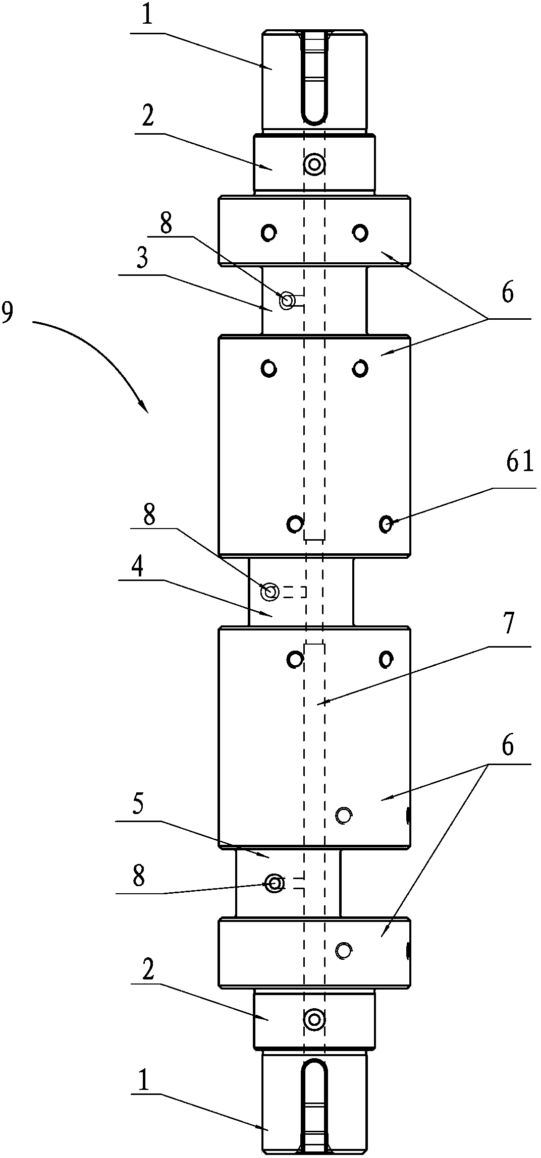
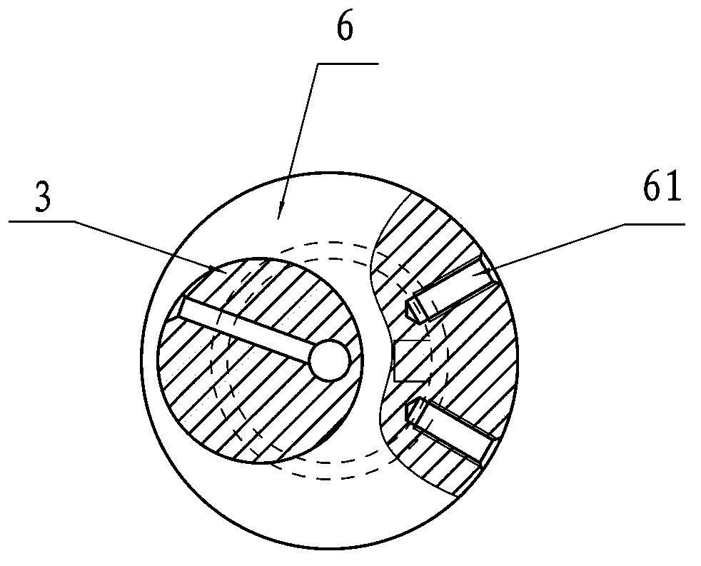
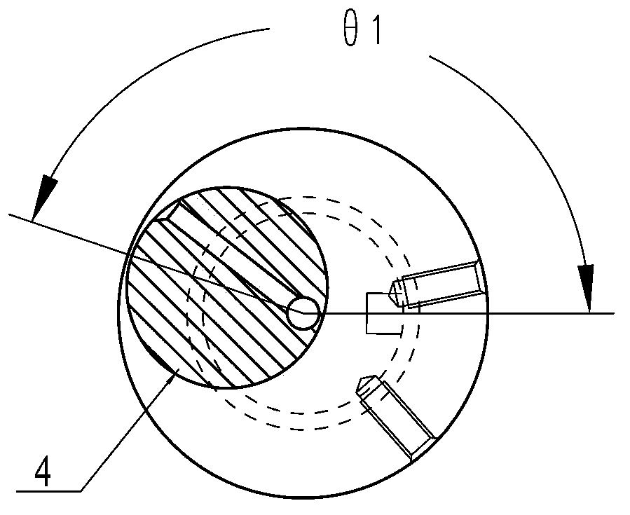
[0022] A crankshaft for a high-speed warp knitting machine, the crankshaft body 9 is as figure 1 As shown, the main components involved include a shaft end 1 , a journal 2 , a first eccentric portion 3 , a second eccentric portion 4 , a third eccentric portion 5 , a balance portion 6 , and an oil channel 7 .

[0023] The crankshaft body 9 is a one-piece structure, and the above-mentioned components are formed as separate parts on the crankshaft body 9 mainly through different outer diameters. First, there are shaft ends 1 and journals 2 at both ends of the crankshaft body 9, and a balance portion 6, a first eccentric portion 3, a second eccentric portion 4, and a third eccentric portion 5 are arranged in the middle part of the crankshaft body 9, Each eccentric portion and balance portion are arranged alternately, so in this embodiment, three eccentric portions are equipped with four balances 6 in total.

[0024] In this embodiment, the outer circle of the journal 2 is φ50mm, ...

Embodiment 2

[0030] A crankshaft for a high-speed warp knitting machine, the crankshaft body 9 is as Image 6 As shown, its principle structure is the same as that of Embodiment 1. The difference is that in this embodiment, the middle part of the crankshaft body 9 has only two eccentric parts and three balance parts 6, and the two eccentric parts can be implemented respectively. In Example 1, any two of the first eccentric part 3 , the second eccentric part 4 , and the third eccentric part 5 can be exchanged, and the installation positions can be exchanged.


PUM


Abstract

The invention mainly discloses a crankshaft used for a high-speed warp knitting machine. A shaft end, a shaft journal, eccentric parts, a balancing part and an oil way channel are arranged on a crankshaft main body. The shaft end and the shaft journal are respectively arranged at the two ends of the crankshaft main body. The eccentric parts and the balancing part are alternately arranged at the middle of the crankshaft main body, and the eccentric parts are at least two in number. The crankshaft can increase the normal production speed and reduce the energy consumption and the maintenance cost of the four-comb warp knitting machine. With the crankshaft disclosed by the invention, a movement control device of the warp knitting machine is spatially compact in structure, smooth and accurate in transmission, low in noise when the warp knitting machine runs at high speed, simple in maintenance and long in service life. Therefore, the production efficiency of the four-comb warp knitting machine is greatly improved.

Description

technical field [0001] The invention relates to a high-speed warp knitting machine knitting motion control device, in particular to a high-speed warp knitting machine with four bars, specifically a crankshaft for a high-speed warp knitting machine. Background technique [0002] The traditional warp knitting machine knitting motion transmission device uses a conjugate cam or an eccentric link mechanism to control the motion of the knitting machine parts. Conjugate cam mechanism has complicated structure and design, requires high manufacturing and assembly precision, and is difficult to control. The noise is large during operation, and the cam is easy to wear during use. After wear, it will have a serious impact on the knitting motion accuracy of the machine, so that the yarn cannot be looped normally during weaving. The eccentric link mechanism is a kind of planar link mechanism. The pressure per unit area of ​​the motion pair is small, and the surface contact is easy to lub...

Claims


Application Information

Patent Timeline
Patent Type & Authority Patents(China)
IPC IPC(8): F16C3/14D04B27/00
Inventor 郑吉华孙剑华
Owner ZHEJIANG YUEJIAN INTELLIGENT EQUIP CO LTD
Learn More