Electromagnetic valve control circuit and electromagnetic valve closing self-checking method thereof

A technology of control circuit and solenoid valve, applied in valve details, valve device, valve operation/release device, etc., can solve the problems of solenoid valve valve blockage, solenoid valve can not be closed, and the signal failure of closing solenoid valve, etc., to achieve safety The effect of high performance, scientific design and simple structure

Active Publication Date: 2012-11-14
HENAN HANWEI ELECTRONICS
View PDF5 Cites 14 Cited by
  • Summary
  • Abstract
  • Description
  • Claims
  • Application Information

AI Technical Summary

Problems solved by technology

[0002] At present, some models of household gas detectors on the market are equipped with a gas solenoid valve linkage control device. Although this type of product can realize gas-off linkage control, the product itself does not have the ability to detect whether the solenoid valve is effectively connected or whether it is effective. Closed detection device or method; the solenoid valve is connected to the corres...

Method used


Image

  • Electromagnetic valve control circuit and electromagnetic valve closing self-checking method thereof

Examples


Embodiment Construction

[0016] The technical solutions of the present invention will be described in further detail below through specific implementation methods.

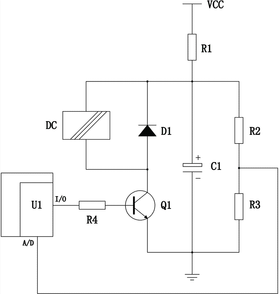
[0017] Such as figure 1 As shown, a solenoid valve control circuit, which includes a microprocessor circuit, solenoid valve DC, diode D1, transistor Q1, polar capacitor C1, current limiting resistor R1, current limiting resistor R4, voltage dividing resistor R2 and sampling resistor R3 .

[0018] Wherein, one end of the current limiting resistor R1 is used to connect to the DC power supply VCC, the other end of the current limiting resistor R1 is connected to one end of the coil of the solenoid valve DC, and the other end of the coil of the solenoid valve DC is connected to the collector of the triode , the emitter of the triode is grounded; the cathode of the diode D1 is connected to one end of the coil of the solenoid valve DC, and the anode of the diode D1 is connected to the other end of the coil of the solenoid valve DC.

[0019] T...


PUM


Abstract

The invention provides an electromagnetic valve control circuit and an electromagnetic valve closing self-checking method thereof. The electromagnetic valve control circuit comprises an electromagnetic valve circuit composed of a microprocessor circuit, an electromagnetic valve, a triode Q 1, a polar capacitor C1, a current limiting resistor R1 and a current limiting resistor R4 and a partial pressure sampling circuit composed of a partial pressure resistor R2 and a sampling resistor R3, wherein the analog-to-digital conversion input end of the microprocessor circuit is connected with one end of the sampling resistor R3. The method comprises the following steps that: a microprocessor U1 controls the conduction and timelag of the triode Q 1, and the sample voltage V1 of the sampling resistor R3 is collected; then, the microprocessor U1 controls the disconnection and timelag of the triode Q 1, controls the conduction and timelag of the triode Q 1, and collects the sample voltage V2 of the sampling resistor R3; and finally, the sample voltage V1 and V2 are compared, if the sample voltages V1 and V2 are the same, the electromagnetic valve is not closed, on the contrary, the electromagnetic valve is already closed. The electromagnetic valve control circuit is scientific in design and high in security; and the method is easy to realize, and occupied system resources are few.

Description

technical field [0001] The invention relates to a control circuit, in particular to a solenoid valve control circuit and a self-checking method for closing the solenoid valve. Background technique [0002] At present, some models of household gas detectors on the market are equipped with a gas solenoid valve linkage control device. Although this type of product can realize gas-off linkage control, the product itself does not have the ability to detect whether the solenoid valve is effectively connected or whether it is effective. Closed detection device or method; the solenoid valve is connected to the corresponding interface of the detector, and the solenoid valve will be closed when the detector alarms. However, in the use of the product, it is inevitable that there will be the following situations: The signal to close the solenoid valve fails; or, when the detector alarms, although the signal to close the solenoid valve is sent, the solenoid valve is blocked by foreign ob...

Claims


Application Information

Patent Timeline
IPC IPC(8): F16K31/06F16K37/00
Inventor 金鑫陈彬王书潜高冰李洛伟邵顺平
Owner HENAN HANWEI ELECTRONICS
Why Eureka
Try Eureka