
Method for stripping photoresist on Array plate

A technology of photoresist and stripping solution, which is applied in the field of LCD, can solve the problems of residual photoresist, difficult to peel off, easy to over-baking, etc.

Active Publication Date: 2014-08-13
TRULY SEMICON
View PDF3 Cites 0 Cited by
  • Summary
  • Abstract
  • Description
  • Claims
  • Application Information

AI Technical Summary

Problems solved by technology

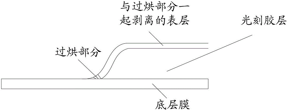
However, because the photoresist in the edge area of ​​the photoresist pattern is relatively thin, or in the step of exposure and development, when the developing solution is not very clean, it is easy to leave a thin layer of photoresist at the via hole. The photoresist with a very thin layer is easy to be overbaked in the post-baking step, which makes it difficult to peel off when reworked, and some photoresist will remain

Method used


Image

  • Method for stripping photoresist on Array plate
  • Method for stripping photoresist on Array plate
  • Method for stripping photoresist on Array plate

Examples


Embodiment Construction

[0029] The following will clearly and completely describe the technical solutions in the embodiments of the application with reference to the drawings in the embodiments of the application. Apparently, the described embodiments are only some of the embodiments of the application, not all of them. Based on the embodiments in this application, all other embodiments obtained by persons of ordinary skill in the art without creative efforts fall within the protection scope of this application.

[0030] The method of the present application is applied in the photoresist stripping repair process of the Array board.

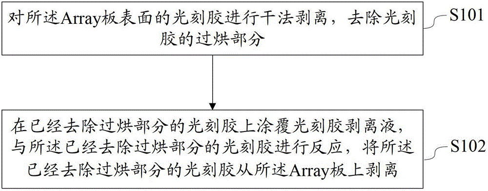
[0031] Such as figure 1 , which shows a flow chart of a stripping method for Array plate photoresist provided in Embodiment 1 of the present application, including:

[0032] Step S101: performing dry stripping of the photoresist on the surface of the Array plate, and removing the overbaked part of the photoresist;

[0033] In this step, the method of dry stripping the ...


PUM


Abstract

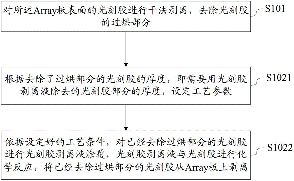
The application discloses a method for stripping a photoresist on an Array plate, which is used for stripping and repairing the photoresist on the Array plate. The method comprises the steps of conducting dry-method stripping on the photoresist on the surface of the Array plate, and removing the over-baking part of the photoresist; coating photoresist stripper on the photoresist with the removed over-baked part, and carrying out a reaction on the photoresist stripper and the photoresist with the removed over-baked part, and stripping the photoresist with the removed over-baked part from the Array plate. The method for stripping the photoresist on the Array plate provided by the application is used for stripping and repairing the photoresist on the Array plate, the photoresist is subjected to the dry-method stripping, an extremely thin layer of over-baked photoresist in the post-baking process can be removed, then the residual photoresist is stripped by utilizing the photoresist stripping liquid, and then the photoresist on the Array plate can be stripped thoroughly.

Description

technical field [0001] This application relates to the field of LCD, more specifically, relates to a stripping method of Array board photoresist. Background technique [0002] LCD (Liquid-Crystal Display) liquid crystal flat-panel display has gradually replaced CRT (Cathode Ray Tube) cathode ray tube display in recent years and has become the mainstream, and has been fully popularized. [0003] In particular, TFT-LCD (Thin-Film Transistor Liquid-Crystal Display) thin film transistor display is rapidly becoming the mainstream product in the new century. [0004] A TFT-LCD panel can be regarded as a layer of liquid crystal sandwiched between two glass substrates. The upper glass substrate is combined with a color filter (Color Filter), while the lower glass is embedded with thin film transistors to form an Array panel. Through the control of the electric field of the pixel by the thin film transistor of the Array board, the deflection of the liquid crystal molecules is contro...

Claims


Application Information

Patent Timeline
Patent Type & Authority Patents(China)
IPC IPC(8): G03F7/42
Inventor 陈建荣刘兴华于春崎任思雨胡君文谢凡李建华
Owner TRULY SEMICON
Learn More