
Cable sheath and core wire stripping and recycling equipment

A technology of cable sheath and recycling equipment, which is applied in the direction of electronic waste recycling, recycling technology, circuits, etc., can solve the problems of reducing recycling efficiency, reducing stripping efficiency, reducing device cost and recycling cost, etc., and achieves convenient cutting and lifting Peeling efficiency and effect of labor reduction

Active Publication Date: 2021-08-24
芜湖市科特电线电缆有限公司
View PDF15 Cites 0 Cited by
  • Summary
  • Abstract
  • Description
  • Claims
  • Application Information

AI Technical Summary

Problems solved by technology

[0004] 1. Usually the cutter is of fixed design and cannot be adjusted according to different types or thickness of cables. Therefore, when cutting the outer sheath of the cable, it is easy to damage the core wire inside the cable, thereby reducing the secondary utilization rate of the core wire
[0005] 2. After the sheath and core wire are separated, they are not collected and treated separately, which reduces the recovery efficiency and easily causes environmental pollution
[0006] 3. The existing peeling equipment is usually composed of multiple independently operating mechanisms, resulting in a large power consumption of the device, and it is not conducive to reducing the cost of the device and recycling costs
[0007] 4. The cutter only cuts once in a single pass. When encountering a cable with a thick sheath, it cannot be cut at one time, thus reducing the stripping efficiency

Method used


Image

  • Cable sheath and core wire stripping and recycling equipment
  • Cable sheath and core wire stripping and recycling equipment
  • Cable sheath and core wire stripping and recycling equipment

Examples


Embodiment Construction

[0043] The technical solutions of the present invention will be further described below in conjunction with the accompanying drawings and through specific implementation methods.

[0044] Wherein, the accompanying drawings are only for illustrative purposes, showing only schematic diagrams, rather than physical drawings, and should not be construed as limitations on this patent; in order to better illustrate the embodiments of the present invention, some parts of the accompanying drawings will be omitted, Enlarged or reduced, does not represent actual product size.

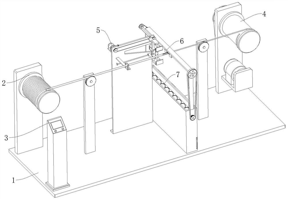
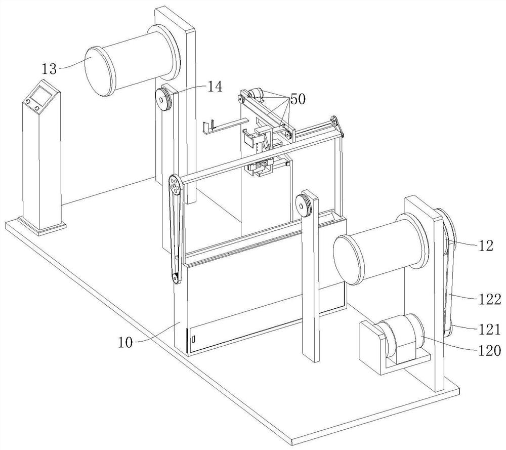
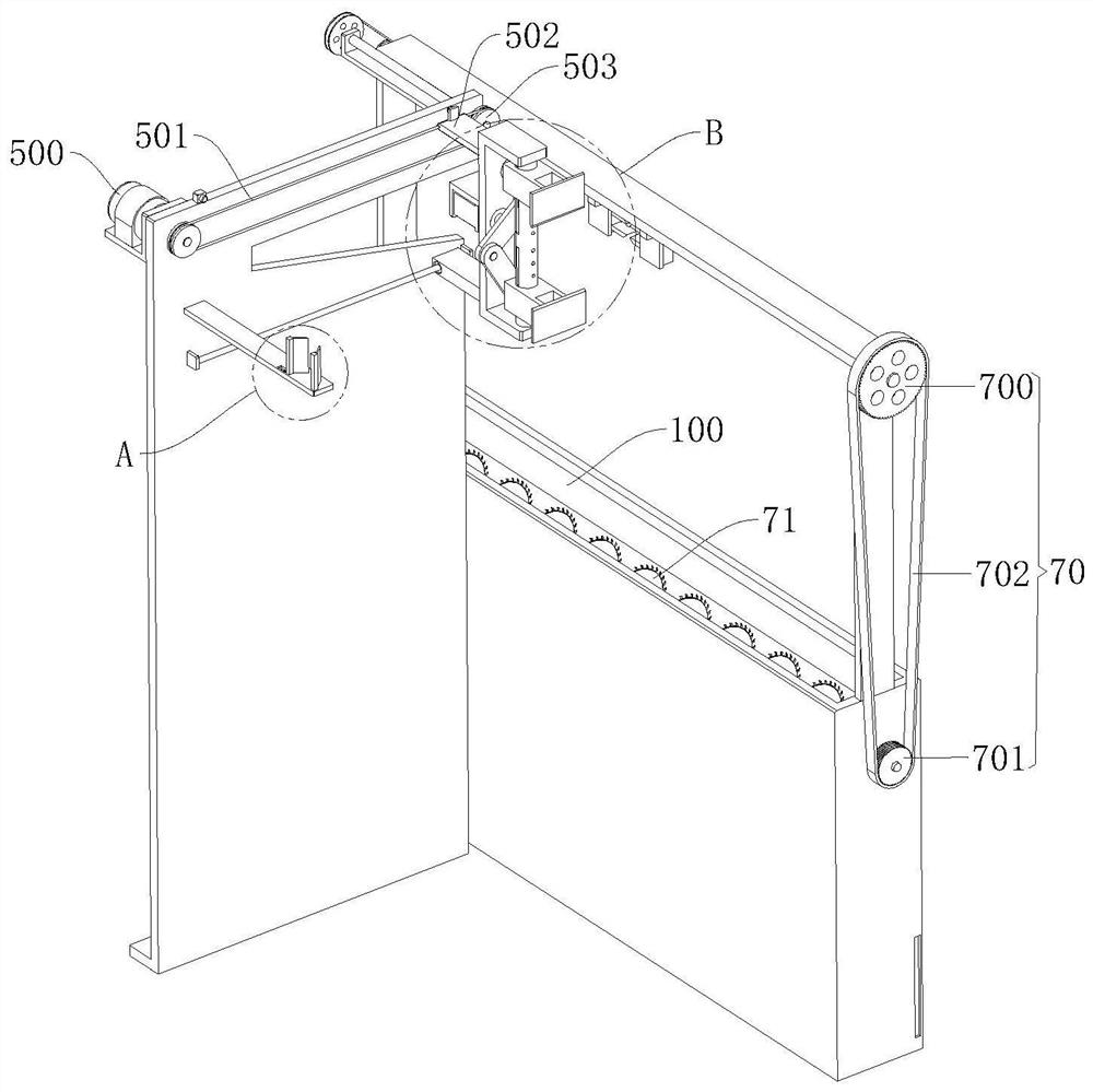
[0045] refer to Figure 1 to Figure 11 The shown cable sheath and core wire stripping recovery equipment includes a base 1 and an unwinding roller 2, and also includes a controller 3, a winding roller 4, a cutting mechanism 5, a pulling mechanism 6 and a crushing mechanism 7. The winding roller 4 is rotatably arranged on the top of the base 1, the top of the base 1 is fixed with a vertical plate, and the cutting ...


PUM


Abstract

The invention relates to the technical field of cable recycling, in particular to cable sheath and core wire stripping and recycling equipment which comprises a base and an unwinding roller and further comprises a controller, a winding roller, a cutting-up mechanism, a pulling mechanism and a crushing mechanism, the cutting-up mechanism comprises a sliding assembly, a telescopic assembly and two cutters, and the pulling mechanism comprises a distance changing assembly and two electric clamping jaws. The crushing mechanism comprises a transmission assembly and a plurality of rotating blades, the rotating blades are arranged at the top of the inner side of the treatment box at equal intervals through a second rotating shaft, the transmission assembly is arranged between the variable-pitch assembly and the rotating blades in a sleeving mode, and the sliding assembly, the telescopic assembly and the two electric clamping jaws are electrically connected with the controller. According to the cable sheath and core wire stripping and recycling equipment, the stripping efficiency is higher, the power consumption is smaller, the manufacturing cost is lower, meanwhile, environmental pollution can be effectively avoided, and the secondary utilization rate of resources can be effectively increased.

Description

technical field [0001] The invention relates to the technical field of cable recycling, in particular to a device for stripping and recycling cable sheaths and core wires. Background technique [0002] The recycling of waste wires and cables is a major issue related to environmental protection and resource utilization. With the rapid development of the national economy, a huge number of waste cables need to be recycled every year. During the use of existing cables, the outside of the cable needs to be The coated insulating protective layer is cut, while the existing cables are only cut with tools when cutting longer cables, which requires a lot of labor, low production efficiency, poor cutting quality, and manual cutting. , there is a greater security risk. [0003] There are following deficiencies in the prior art: [0004] 1. Usually the cutter is of fixed design and cannot be adjusted according to different types or thickness of cables. Therefore, when cutting the outer...

Claims


Application Information

Patent Timeline
Patent Type & Authority Applications(China)
IPC IPC(8): H01B15/00
CPCH01B15/006H01B15/008Y02W30/82
Inventor 冯林静冯林丽
Owner 芜湖市科特电线电缆有限公司
Learn More