Drive circuit for OLED (Organic Light Emitting Diode) panel

A driving circuit and panel technology, applied in the field of OLED panels, can solve the problems of large dynamic loss, high temperature rise, uneven display, etc., and achieve the effect of reducing dynamic loss and lowering operating temperature

Inactive Publication Date: 2012-11-14
AU OPTRONICS CORP
View PDF0 Cites 14 Cited by
  • Summary
  • Abstract
  • Description
  • Claims
  • Application Information

AI Technical Summary

Problems solved by technology

However, due to the process differences among multiple TFTs, it is easy to cause uneven display. One solution to the traditional OLED panel is: first, use the reset signal to release the residual charge of the OLED and TFT; The compensation voltage is stored in the pixel capacitor; then, the data voltage is written into the pixel capacitor; finally, the V of the TFT is determined by the capacitance stored in the pixel capacitor GS , and then determine the size of the current flowing through the OLED to adjust the brightness of the OLED panel
In this way, a reference voltage needs to be output during the reset phase and compensation phase, and a data voltage needs to be output during the data writing phase, causing the output terminal of the operational amplifier to continuously switch between the reference voltage and the data voltage, resulting in a large dynamic loss and higher temperature rise

Method used


Image

  • Drive circuit for OLED (Organic Light Emitting Diode) panel
  • Drive circuit for OLED (Organic Light Emitting Diode) panel
  • Drive circuit for OLED (Organic Light Emitting Diode) panel

Examples


Embodiment Construction

[0030] In order to make the technical content disclosed in this application more detailed and complete, reference may be made to the drawings and the following various specific embodiments of the present invention, and the same symbols in the drawings represent the same or similar components. However, those skilled in the art should understand that the examples provided below are not intended to limit the scope of the present invention. In addition, the drawings are only for schematic illustration and are not drawn according to their original scale.

[0031] The specific implementation manners of various aspects of the present invention will be further described in detail below with reference to the accompanying drawings.

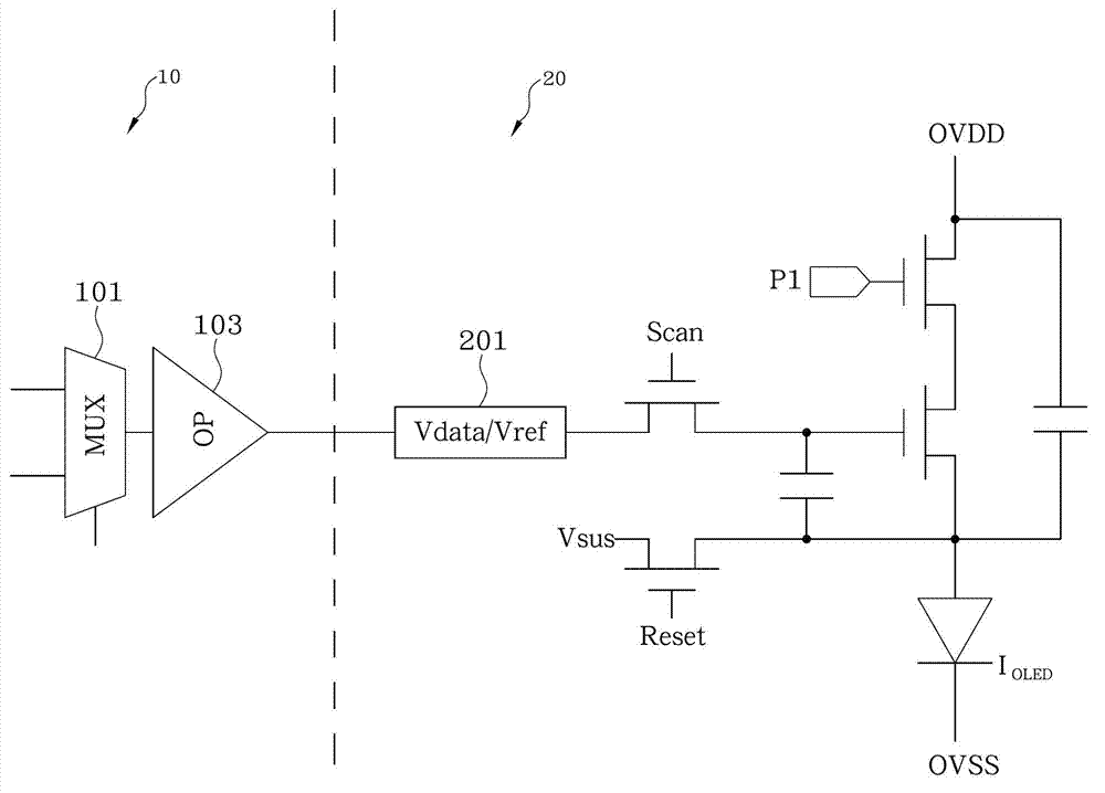
[0032] figure 1 A schematic structural diagram of a driving circuit for an OLED (Organic Light Emitting Diode, organic light emitting diode) panel in the prior art is shown. refer to figure 1 , the conventional drive circuit includes two parts, the sourc...


PUM


Abstract

The invention provides a drive circuit for an OLED (Organic Light Emitting Diode) panel. The drive circuit comprises a line buffer and an output buffer. The input end of the line buffer is used for receiving a data voltage signal; the output buffer is electrically connected to the line buffer, a first multiplexer of the output buffer outputs one of the data voltage signal and the reference voltage signal through a first enable signal, and a second multiplexer of the output buffer outputs the other one of the data voltage signal and the reference voltage signal through a second enable signal. The first multiplexer outputs the data voltage signal and the reference voltage signal in a staggered manner, and the second multiplexer outputs the reference voltage signal and the data voltage signal in a staggered manner. With the adoption of the drive circuit provided by the invention, the first multiplexer and the second multiplexer of the output buffer output the data voltage signal and the reference voltage signal in a staggered manner, so that two channels can be used for the charge sharing operation when the first multiplexer and the second multiplexer are switched, since each channel only takes charge of half voltage variation when sharing charges, dynamic loss of the circuit can be reduced effectively, and the work temperature of the circuit can be reduced.

Description

technical field [0001] The invention relates to an OLED panel, in particular to a source driving circuit in the OLED panel. Background technique [0002] Currently, the OLED (Organic Light Emitting Diode) display has the characteristics of self-luminescence, which can save the weight, volume and power consumption of the backlight module, so it is not only thinner than the Liquid Crystal Display (LCD), but also The operating voltage can be reduced to 2V to 10V. In addition, OLED has a wide viewing angle, fast picture response (such as less than 10ms) and better color performance than LCD, and has a bendable feature, which makes its application range extremely wide. It has been used in handheld devices such as mobile phones and personal digital assistants. Display panels for electronic products. [0003] As we know, OLED panels use organic light-emitting diodes as light-emitting components, and organic light-emitting diodes are components driven by current, and their luminou...

Claims


Application Information

Patent Timeline
Patent Type & Authority Applications(China)
IPC IPC(8): G09G3/32G09G3/3208
Inventor 杨智富杜明鸿何宇玺
Owner AU OPTRONICS CORP
Why Eureka
Try Eureka