Capturing device for magnetic impurities in liquid metal

A liquid metal, magnetic impurity technology, applied in high gradient magnetic separators and other directions, can solve the problems of less research, unpublished service performance results of magnetic traps, and few patent results, and achieve the effect of increasing the strength of the air gap magnetic field

Inactive Publication Date: 2012-11-21
HEFEI INSTITUTES OF PHYSICAL SCIENCE - CHINESE ACAD OF SCI
View PDF6 Cites 3 Cited by
  • Summary
  • Abstract
  • Description
  • Claims
  • Application Information

AI Technical Summary

Problems solved by technology

The Karlsruhe Institute of Technology in Germany has designed and studied a similar device—a magnetic trap is used in a high-temperature liquid metal circuit. The magnetic trap separation space used is an empty flow channel. The magnetic trap in a liquid metal circuit of the unit Magnetic impurities were captured, but no impurities were found when the magnetic trap in another loop was disassembled several times. One of the possible reasons is that the successful application of oxygen measurement and control technology in this loop makes the impurities including magnetic impurities produced by corrosion negligible. Another possible reason is that there are some improvements to be made in the design of the magnetic trap of this circuit; there is also a magnetic trap device in a l

Method used


Image

  • Capturing device for magnetic impurities in liquid metal
  • Capturing device for magnetic impurities in liquid metal
  • Capturing device for magnetic impurities in liquid metal

Examples


Embodiment Construction

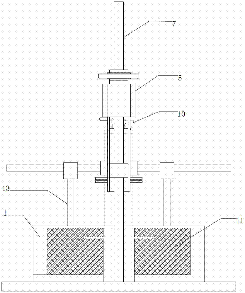
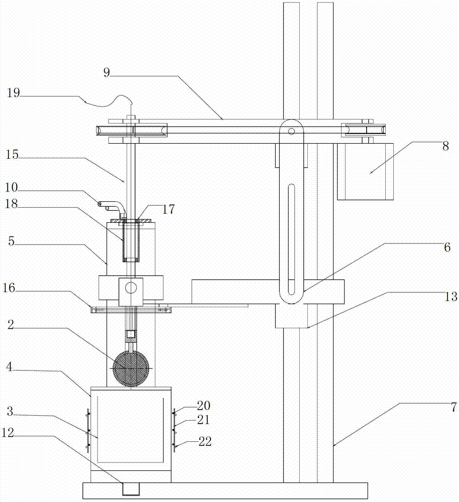
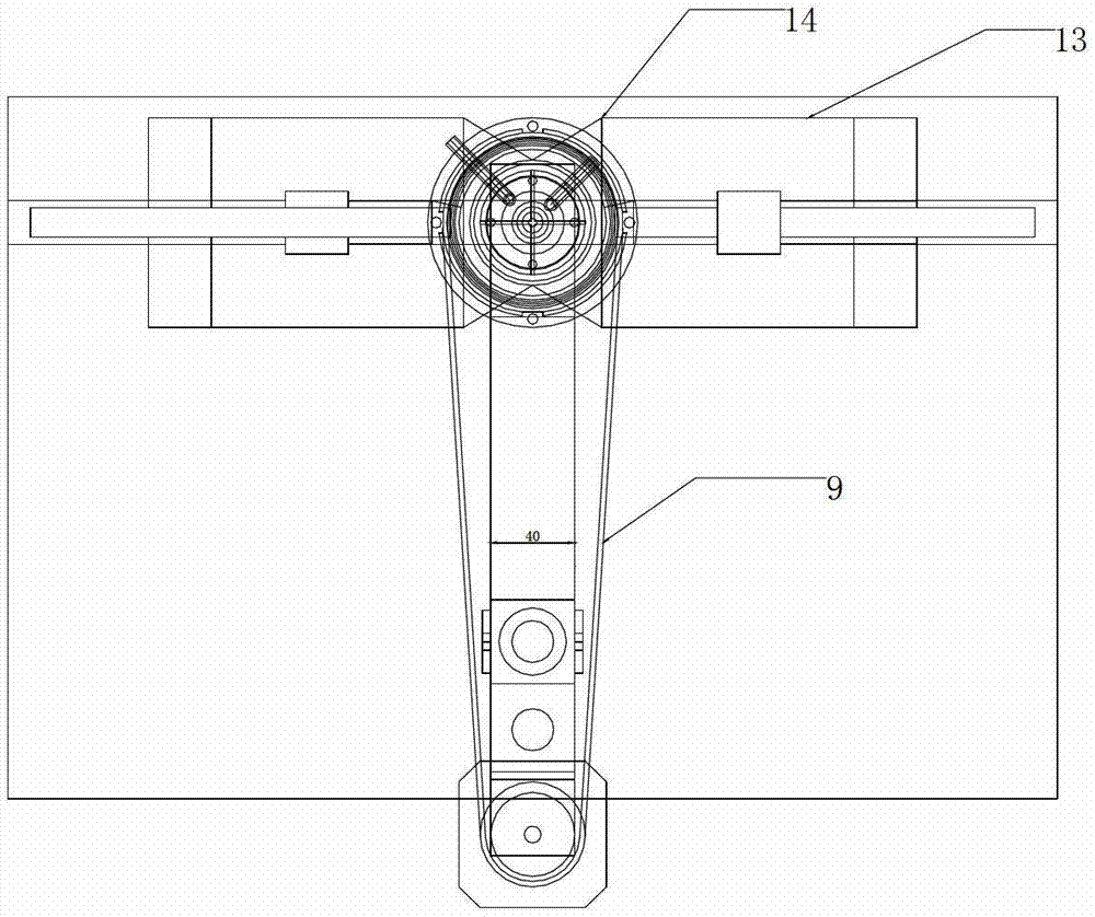
[0030] Depend on Figure 1-4 It can be seen that the embodiment of the present invention includes: a magnetic field system 1 , a wire mesh 2 , a crucible 3 , a melting tank 4 , a sealing system 5 , a fastening link 6 , a support stand 7 , a motor 8 , a belt 9 and a gas inlet and outlet 10 . Depend on Figure 1-3 It can be seen that the magnetic field system 1 has two permanent magnets 11 of the same specification, the permanent magnets 11 are placed in the limit slider 13 on the guide rail 12 , and the magnetic field is provided by the yoke 14 . Depend on figure 2It can be seen that the crucible 3 is placed in the melting tank 4, the wire mesh 2 is vertically placed in the liquid metal in the crucible 3 through the rotating shaft 15, and the heating wire 20, the thermal insulation material 21 and the cooling water copper pipe 22 are arranged in sequence outside the melting tank 4 Sealing system 5 is made up of rotating shaft 15, sealing flange 16, copper sleeve 17 and seali...


PUM


Abstract

A capturing device for magnetic impurities in liquid metal comprises a magnetic field system, a wire net, a crucible, a smelting tank, a sealing system, a fastening connecting rod, a support platform, a motor, a belt and a gas passageway; permanent magnets in the magnetic field system are placed in limit slide blocks on a guide rail and provide a magnetic field through a magnetic yoke; the crucible is arranged in the smelting tank as a liquid metal container; the wire net is vertically arranged in liquid metal through a rotating shaft; the sealing system comprises a sealing flange, the rotating shaft, a copper sleeve and a sealing oil trough; the position of the wire net in the liquid metal can be changed by adjusting the lifting height of the rotating shaft, and the fastening connecting rod is fixed through a fastening screw so as to fix the rotating shaft; the motor drives the rotating shaft through the belt; and the gas passageway is arranged at the upper end of the sealing oil trough and is used for allowing liquid metal protective gas to pass in and out. The capturing device for magnetic impurities can be used for simulating part of working parameters of magnetic traps in liquid metal and capturing magnetic impurities and is a simple and effective device for research on action of magnetic impurities in liquid metal.

Description

technical field [0001] The invention relates to a capture device for magnetic impurities in liquid metal, which belongs to a simple, energy-saving high-gradient magnetic purification device and is suitable for capturing and researching magnetic impurities in liquid metal. Background technique [0002] Using the magnetic differences of various minerals, the method of mineral separation in a non-uniform magnetic field is magnetic separation. At present, magnetic separation is widely used, such as the separation and removal of non-ferrous and rare metals and non-metallic ores, the removal of magnetic components in solid materials, and the removal of impurities in production and domestic sewage. The magnetic separation process is essentially magnetic force and fluid resistance. The process of mechanical forces such as gravity competing with each other, when the mechanical force on the material in the non-uniform magnetic field is less than the magnetic force, the material will b...

Claims


Application Information

Patent Timeline
IPC IPC(8): B03C1/025B03C1/031
Inventor 王艳青李强徐敬尧刘少军黄群英
Owner HEFEI INSTITUTES OF PHYSICAL SCIENCE - CHINESE ACAD OF SCI
Why Eureka
Try Eureka