MOSFET (metal-oxide-semiconductor field effect transistor)-based inverter type welding equipment by sdie inlet air

A welding equipment and inverter technology, which is applied in the field of inverter welding equipment, can solve problems such as poor heat dissipation of high-frequency transformer components, uneven heat dissipation of MOSFETs, and poor consistency of multi-tube correlations, etc., so as to improve load duration and improve Cooling conditions, various effects of functions

Inactive Publication Date: 2012-11-21
王明伟
View PDF5 Cites 10 Cited by
  • Summary
  • Abstract
  • Description
  • Claims
  • Application Information

AI Technical Summary

Problems solved by technology

[0007] 3. The secondary rectification circuit adopts multiple associations of fast recovery diodes. Due to the poor consistency of the multi-tube associations, it is necessary to strictly select the electrical parameters, and it is easy to be damaged when the matching is not good.
[0008] 4. Poor heat dissipation results in low load duration, short allowable working cycle and low working efficiency
[0009] 5. Due to the large number of MOSFET devices, which are distributed in a large range, the frontal air intake is generally used for cooling. The air flow path is long and the heat transfer capacity is poor, which may easily cause uneven heat dissipation of MOSFETs, high-frequency transformers, rectifiers and other components. bad
[0010] 6. Usually, it is necessary to use a large-volume radiator and hardware structure, which has a single structure, heavy weight, and high manufacturing cost

Method used


Image

  • MOSFET (metal-oxide-semiconductor field effect transistor)-based inverter type welding equipment by sdie inlet air
  • MOSFET (metal-oxide-semiconductor field effect transistor)-based inverter type welding equipment by sdie inlet air
  • MOSFET (metal-oxide-semiconductor field effect transistor)-based inverter type welding equipment by sdie inlet air

Examples


Embodiment Construction

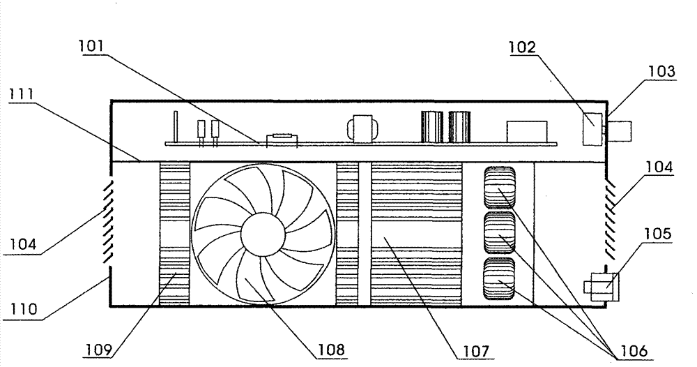
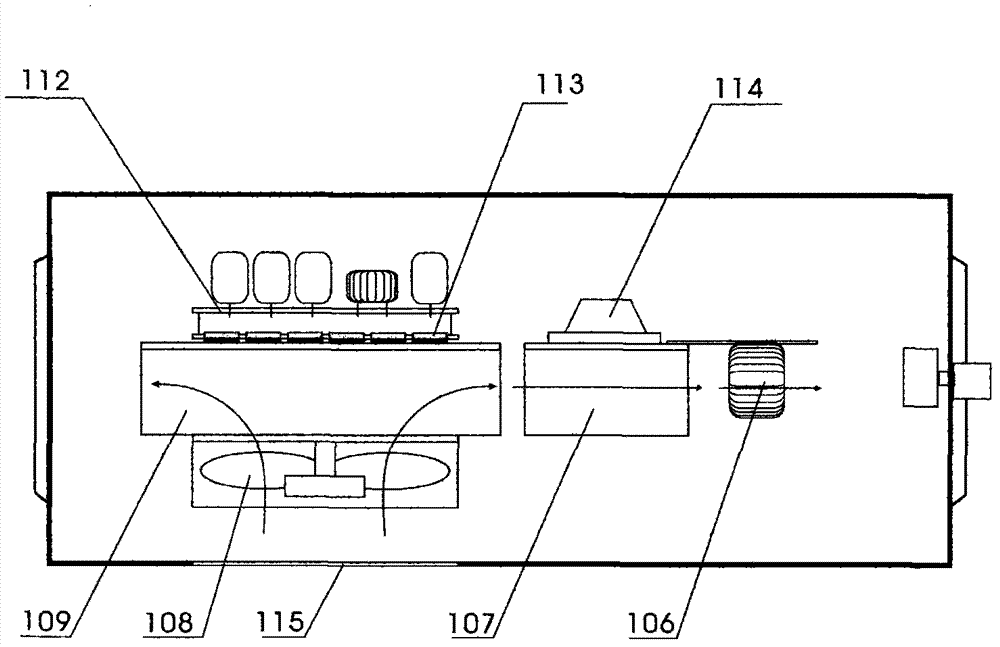
[0035] Picture 1-1 It is a side view of the basic structure diagram of the inverter welding equipment with side air intake, Figure 1-2 It is a top view of the distribution of cooling components in the space below the partition. Figure 1-2 The direction of the arrow in is the direction of cooling air flow.

[0036] In the figure, 101 is the control circuit board, 102 is the control knob, 103 is the front panel, 104 is the air outlet, 105 is the welding output terminal, 106 is the high-frequency transformer, 107 is the rectifier module radiator, 108 is the fan, 109 is the inverter Module radiator, 110 is the rear panel, 111 is the partition; 112 is the driver board, 113 is the MOSFET device, 114 is the rectifier module, 115 is the air inlet.

[0037]Wherein the MOSFET devices 113 are installed on the circuit board in groups, and then fixed on the plane side of the E-type radiator 109, the heat dissipation surface of the MOSFET device is located on the same plane, and its hea...


PUM


Abstract

The invention discloses inverter type welding equipment by using side inlet air. The inverter type welding equipment comprises a front panel, a rear panel, a rectifier and filter circuit, a control module, a driver module, MOSFET (metal-oxide-semiconductor field effect transistor) devices, an inverter module, a rectifier module, a high-frequency transformer, a current regulating device, an input power line, an output port, a fan, a rack and the like. The inverter type welding equipment is chracterized in that the fan is installed at the side of the rack, air outlets are arranged on the front panel and the rear panel, heat-transfer surfaces of the MOSFET devices are arranged on an identical plane which keeps close thermal contact with one same plane of E-shaped heat sinks and forms the inverter module by being installed together with a driver plate, a rectification module and the heat sinks are installed together to form the rectifier module, the fan is arranged above fins of the E-shaped heat sinks of the inverter module, airstream flows vertically to the fins of the heat sinks and flows along a flow channel formed by the fins of the heat sinks so as to continue to cool the rectification module and a main transformer; the airstream is discharged out of the rack from the air outlets on the front panel and the rear panel, so as to form the inverter type welding equipment which has high heat dissipation efficiency, high load rate and simple structure, and is stable and reliable.

Description

technical field [0001] The invention relates to an inverter welding equipment using MOSFET (field effect transistor) as a driving device. This welding equipment can be used for welding metal materials. Weight, increased load duration, and reduced manufacturing costs. The welding equipment formed by adopting the technology of the invention has the characteristics of portability, energy saving, multiple functions, safety and reliability, and low cost. Background technique [0002] The existing inverter welding equipment is divided into IGBT module type and MOSFET discrete component type. The advantages of the former are simple structure, uniform and convenient heat dissipation, but due to low operating frequency, large volume and high cost; the advantage of the latter is high operating frequency , Low cost of materials, small size, light weight, and light weight, but the circuit and structure are more complicated. [0003] Existing MOSFET welding equipment usually adopts the...

Claims


Application Information

Patent Timeline
Patent Type & Authority Applications(China)
IPC IPC(8): B23K9/10B23K9/32B23K37/00
Inventor 王明伟
Owner 王明伟
Why Eureka
Try Eureka