Method and device for design of electronic design automation (EDA) tool of multi-field programmable gate array (FPGA) system

A design method and tool technology, applied in computing, instrumentation, electrical and digital data processing, etc., can solve the problems of increasing the difficulty and complexity of layout and wiring, the number of connections, and the lack of clear and independent functions of the FPGA chip, and achieve the design process. clear and clear effect

Active Publication Date: 2012-11-21
锐立平芯微电子(广州)有限责任公司
View PDF5 Cites 24 Cited by
  • Summary
  • Abstract
  • Description
  • Claims
  • Application Information

AI Technical Summary

Problems solved by technology

[0011] However, the existing technology still has the following disadvantages: the segmentation process is divided at the register level, but not divided according to the module, so that the number of connections between the divided netlists is large and the functions of each FPGA chip in the multi-FPGA system are not clear enough independent
In the layout and routing process, the entire multi-FPGA system is used as the object, which increases the difficulty and complexity of layout and routing.

Method used


Image

  • Method and device for design of electronic design automation (EDA) tool of multi-field programmable gate array (FPGA) system
  • Method and device for design of electronic design automation (EDA) tool of multi-field programmable gate array (FPGA) system
  • Method and device for design of electronic design automation (EDA) tool of multi-field programmable gate array (FPGA) system

Examples


Embodiment Construction

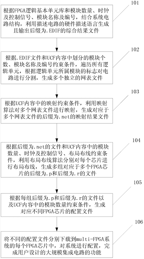
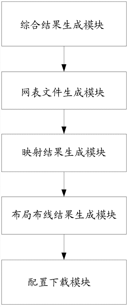
[0040] In order to deeply understand the present invention, the present invention will be described in detail below in conjunction with the accompanying drawings and specific embodiments.

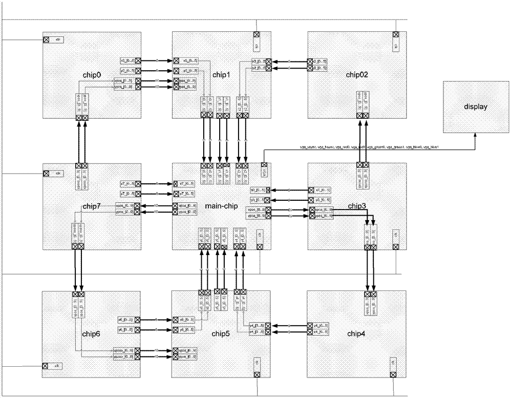
[0041]Before designing the EDA tool of the multi-FPGA system, the user needs to set the content of the user constraint file (UCF, User Constraint File) according to the format specified by the EDA tool and the content of the circuit design. The content of UCF includes: according to the structure of the multi-FPGA system, set the number of modules N (N is a natural number) divided into the system, that is, the number of FPGA chips, including a main module and several sub-modules; system clock and Control signals, including the name and frequency of the clock signal, and the name and frequency of the control signal, the control signal includes the set signal and reset signal; the module name and number, including the name of each module and its corresponding function in the multi-FPGA system ...


PUM


Abstract

The invention discloses a method and a device for design of an electronic design automation (EDA) tool of a multi-field programmable gate array (FPGA) system and belongs to the technical fields of field programmable gate array and electronic design automation design. The method includes: generating a comprehensive result file according to FPGA logic basic unit database and constraint conditions; dividing circuits according to the comprehensive result file and the constraint conditions, and generating a plurality of netlist files; mapping each netlist file and generating a mapping result file according to the constraint conditions; performing layout and wiring and generating a layout wiring result file according to the mapping result file and the constraint conditions; and generating a configuration file and downloading the configuration file to an FPGA chip according to the layout wiring result file and the constraint conditions. The device for design of the EDA tool of the multi-FPGA system is further provided. A whole design process of the multi-FPGA system is clear through user intervention and with the help of guidance of a user constraint file.

Description

technical field [0001] The invention relates to the field programmable gate array and its supporting electronic design automation design technical field, in particular to an EDA tool design method and device for a multi-FPGA system. Background technique [0002] With the increasing cost of application-specific integrated circuit (ASIC, Application Specific Integrated Circuit) masks, and the gradual reduction of the performance gap between Field Programmable Gate Array (FPGA, Field Programmable Gate Array) and ASIC, FPGA chips have a market The major advantages such as short cycle time and low template cost make FPGA gradually become a platform for various real-time designs. [0003] At present, there are still certain challenges in using FPGA to complete the design of large-scale single-chip systems (SoC, System-On-a-Chip). One of the difficulties is that FPGAs have limited resources compared to ASICs. During the ASIC design process, designers do not need to worry about t...

Claims


Application Information

Patent Timeline
IPC IPC(8): G06F17/50
Inventor 张倩莉李艳陈亮于芳
Owner 锐立平芯微电子(广州)有限责任公司
Why Eureka
Try Eureka