Eureka AIR delivers breakthrough ideas for toughest innovation challenges, trusted by R&D personnel around the world.

Combined heat exchanger system

A heat exchanger, composite technology, applied in the direction of indirect heat exchanger, heat exchanger type, machine/engine, etc., can solve the difficulty of ensuring the size of the space required for heat exchange and the reduction of the heat exchange rate of the heat exchanger , deterioration of heat transfer rate, etc., to achieve the effect of improving vehicle installability, reducing installation space, and securing the required space

Inactive Publication Date: 2012-11-28
CALSONIC KANSEI CORP
View PDF7 Cites 3 Cited by
  • Summary
  • Abstract
  • Description
  • Claims
  • Application Information

AI Technical Summary

Problems solved by technology

Therefore, when the heat exchangers are arranged in the front-rear direction of the vehicle in order to secure the arrangement space, for example, when a large number of heat exchangers must be installed like a hybrid vehicle, the number of heat exchanger layers in the vehicle front-rear direction increases, The heat transfer rate of the heat exchanger on the downstream side of the cooling air decreases
[0011] On the other hand, when it is desired to reduce the number of heat exchanger layers in the front and rear directions of the vehicle, it is necessary to squeeze multiple heat exchangers into the same plane in the vehicle width direction, and it is difficult to secure the required space for heat exchange.
[0012] In this way, the greater the number of heat exchangers, the larger the overall size of the heat exchangers, the more difficult it is to ensure the space required for the installation of heat exchangers, and the increase in the number of heat exchanger layers in the front and rear directions of the vehicle will increase the size of the heat exchanger assembly. Difficulty inside the vehicle and worsens the heat transfer rate
[0013] In the technology described in the above-mentioned patent document 3, a lot of piping work is required, and the work is cumbersome.

Method used


Image

  • Combined heat exchanger system

Examples


Embodiment 1

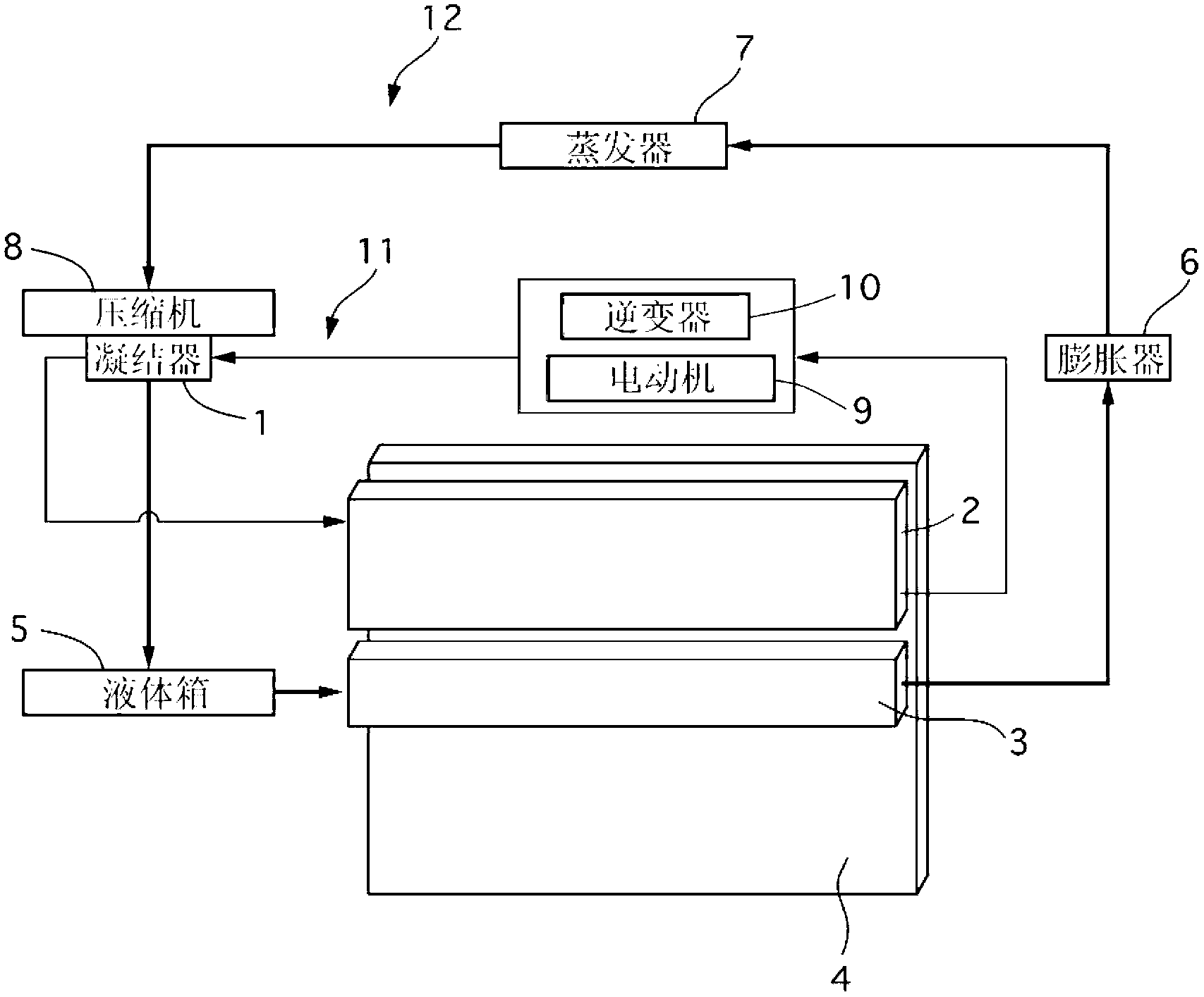
[0063] First, the overall structure of the composite heat exchanger of Example 1 will be described.

[0064] The composite heat exchanger of this embodiment 1 includes a condenser (equivalent to the first heat exchanger of the present invention) 1, an auxiliary radiator (equivalent to the second heat exchanger and radiator of the present invention) 2, a low temperature treatment condensation Heater 3 (corresponding to the third heat exchanger and radiator of the present invention), main radiator 4 (corresponding to the fourth heat exchanger and main radiator of the present invention), liquid tank (corresponding to the storage part of the present invention) 5. Expander 6, evaporator 7 and compressor 8. This composite heat exchanger is installed in a hybrid vehicle driven by an engine (internal combustion engine) and an electric motor 9, and uses the main radiator 4 to cool the unillustrated engine, and uses the sub-radiator 2 to cool the electric motor 9, etc. Use the condense...


PUM


Abstract

A combined heat exchanger system includes a first heat exchanger (1) for cooling a first cooling medium, a second heat exchanger (2) for cooling a second cooling medium, and a compressor (8) for compressing the first cooling medium to be supplied to the first heat exchanger (1). The first heat exchanger (1) is separated from the second heat exchanger (2), being integrally assembled with the compressor (8) in such a way that the first compressor (1) can be directly and fluidically connected with the compressor (8). The first heat exchanger (1) liquid-cools the first cooling medium, which is outputted from the compressor (8), by using the second cooling medium that is cooled by the second heat exchanger (2).

Description

technical field [0001] The present invention relates to a composite heat exchanger having a plurality of heat exchangers respectively connected to, for example, an engine, an air conditioning system, and the like. Background technique [0002] Such a conventional compound heat exchanger described in Patent Document 1 is known. [0003] This conventional composite heat exchanger includes a first air-cooled heat exchanger (sub-radiator) for cooling cooling water for heating elements other than the engine, and a second air-cooled heat exchanger (condenser) for cooling refrigerant for vehicle air conditioning. radiator) and the third air-cooled heat exchanger (radiator) that cools the cooling water of the engine. The first air-cooled heat exchanger and the third air-cooled heat exchanger include: a core formed by laminating main sheets and cooling fins; and left and right cooling tanks connected to each other via the main sheet. The width of the core of the third air-cooled he...

Claims


Application Information

Patent Timeline
Patent Type & Authority Applications(China)
IPC IPC(8): B60K11/04B60H1/32F25B6/04
CPCB60K11/02B60K6/20F01P2003/187F01P3/18F01P2050/24F28D1/0452F28D2021/0084B60H1/00878B60H2001/00307B60H2001/00928F25B2339/047F25B2400/071
Inventor 增田晃稻叶浩行羽田智川口达生渡边年春津田昌宏
Owner CALSONIC KANSEI CORP
Why Eureka
Eureka Blog
Learn More