Capacitance type rotary encoder and method for sensing rotation angle
A rotary encoder and capacitive technology, applied in the direction of converting sensor output, using electric/magnetic devices to transmit sensing components, instruments, etc., can solve the problems of large volume and complex structure of capacitive rotary encoders, and achieve small size, The effect of simple structure
- Summary
- Abstract
- Description
- Claims
- Application Information
AI Technical Summary
Problems solved by technology
Method used
Image

Examples
Embodiment 1
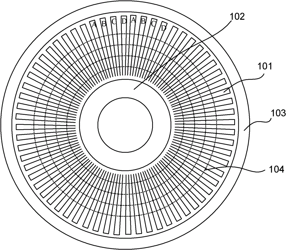
[0075] figure 1 It is a schematic diagram of the static plate of the capacitive rotary encoder in Embodiment 1 of the present invention. It is a transmitter and receiver used as an encoder.
[0076] Such as figure 1 As shown, the same conductive electrodes 101 are arranged on a stationary plate. Every four consecutive electrodes form a space cycle, as shown in the figure, every four electrodes A, B, C, D form a space cycle. The four electrodes in each cycle are respectively excited by four different signals. In this embodiment, there are four wires 104 on the side different from the static board (when the printed circuit board has only one layer) or on a layer of different layers (when the printed circuit board has multiple layers), corresponding to these four different wires 104 respectively. Stimulate electrical signals. The signal generator provides four AC excitations with different phases, which are respectively loaded on the four wires 104 . The phase difference of...
Embodiment 2
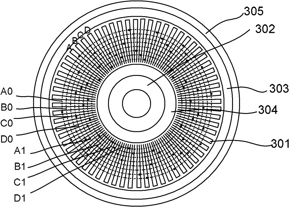
[0116] image 3 A schematic diagram of a static plate of a capacitive rotary encoder provided by Embodiment 2 of the present invention.
[0117] Such as image 3 As shown, the emission area is provided with 64 radially arranged electrodes 301 to form a track. The 8 signal lines A0, A1, B0, B1, C0, C1, D0, and D1 are arranged on the other layer of the static board, and are divided into two groups: 1 series (A1, B1, C1, D1) and 0 series (A0, B0, C0, D0). Note that the signal line in the embodiment of the present invention is a ring, but in other embodiments, the signal line can also be in other shapes and forms. Each electrode 301 is connected to a corresponding signal line through a via hole.
[0118] Every four consecutive electrodes A, B, C, and D constitute a space period, which are respectively excited by an orthogonal four-phase (A phase, B phase, C phase, D phase) AC voltage source. The excitation signal of each phase is respectively connected to two signal lines, fo...
Embodiment 3
[0132] Figure 7 A schematic diagram of a static plate of a capacitive rotary encoder provided by Embodiment 3 of the present invention.
[0133] Figure 7 An embodiment of a static plate with higher precision or larger diameter is given. The number of electrodes 701 is 128, but the present invention is not limited to this number. Since the number of detected code bits in absolute mode determines the maximum number of unique positions that can be distinguished in absolute mode. Increasing the accuracy of the encoder or increasing the diameter of the encoder requires more bits. The detected code bits are increased by increasing the number of sector-shaped conductive regions. Specifically, as in the above example, each sector-shaped conductive area can provide a 3-bit effective code, then three sector-shaped conductive areas can provide a 9-bit effective code, that is, 2^9=512 absolute positions can be distinguished. The ring-shaped conductive area 702 on the static plate i...
PUM
 Abstract
Description
Claims
Application Information