
Random fiber laser

A technology of fiber lasers and lasers, applied in lasers, laser components, phonon exciters, etc., can solve the problem of low pump light utilization

Inactive Publication Date: 2012-11-28
BEIJING UNIV OF CHEM TECH
View PDF4 Cites 13 Cited by
  • Summary
  • Abstract
  • Description
  • Claims
  • Application Information

AI Technical Summary

Problems solved by technology

[0005] 2. The output power of the laser needs to be further improved
[0006] 3. The utilization rate of pump light is low

Method used


Image

  • Random fiber laser
  • Random fiber laser

Examples


Embodiment Construction

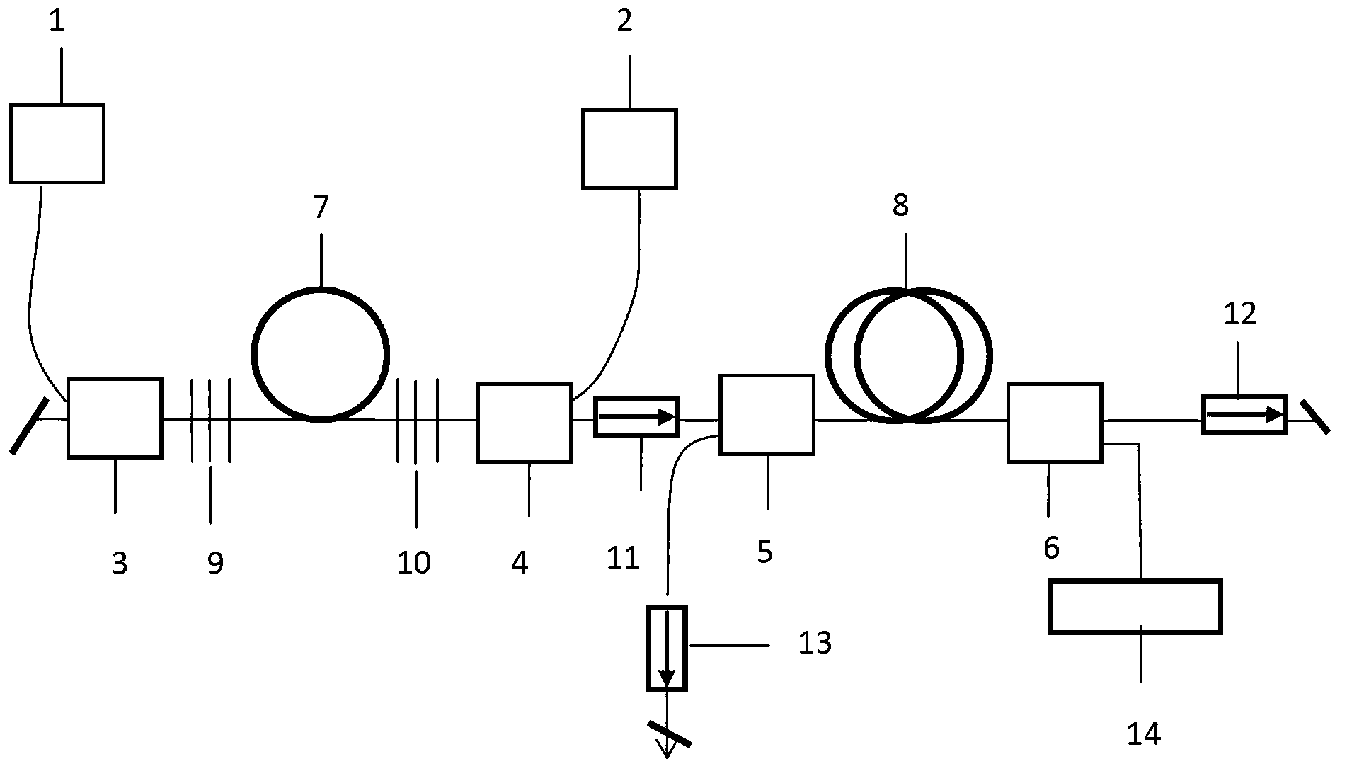
[0041] The following first combines the attached figure 1 A detailed description of the specific implementation of the system solution one:

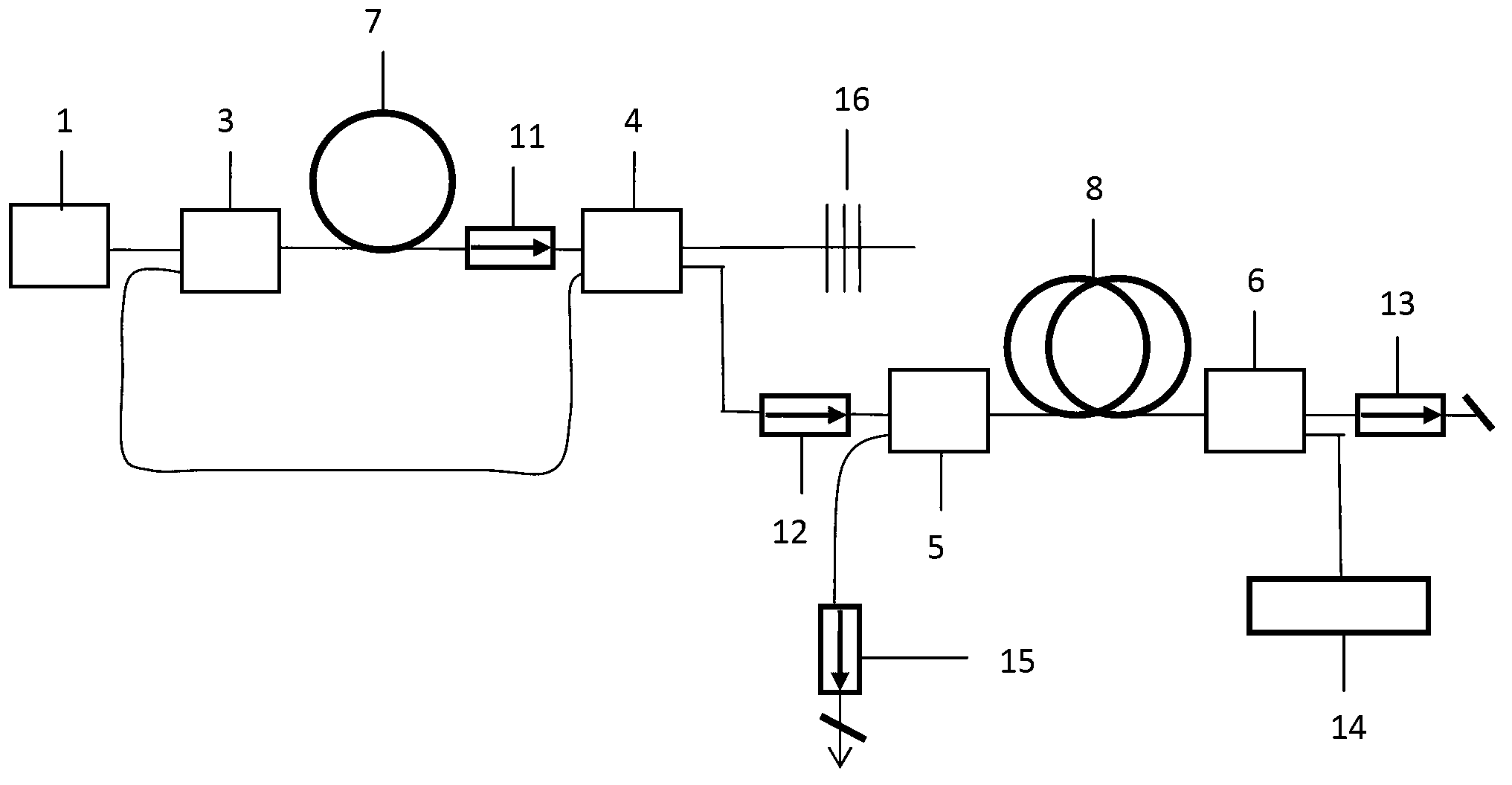
[0042] In this scheme, a random fiber laser system based on a linear cavity fiber laser is used. For the system, see figure 1 , including a first semiconductor laser 1, a second semiconductor laser 2, a first coupler 3, a second coupler 4, a third coupler 5, a fourth coupler 6, a first optical fiber 7, a second optical fiber 8, a first A fiber grating 9 , a second fiber grating 10 , a first optical isolator 11 , a second optical isolator 12 , a third optical isolator 13 , and a pump light reflector 14 .

[0043] A linear cavity fiber laser is composed of a first semiconductor laser 1 , a second semiconductor laser 2 , a first coupler 3 , a second coupler 4 , a first optical fiber 7 , a first fiber grating 9 and a second fiber grating 10 . The laser light emitted by the first semiconductor laser 1 and the second semiconductor laser 2 is...


PUM


Abstract

The invention discloses a random fiber laser system. According to the system, an optical fiber serves as a laser medium, and a fiber laser comprising a crystal fiber laser, a nonlinear fiber laser, a rare earth doped fiber laser and a plastic fiber laser serves as pump light to be coupled into the optical fiber. Because the refractive index of the optical fiber has non-uniformity and is randomly distributed along the optical fiber, so that the photon is subjected to rayleigh scattering during transmission in the optical fiber; and moreover, the pump light provides gain for the backward scattered light along the optical fiber, when the overall gain is greater than the total loss, the backward scattered light is amplified to form random laser. A discrete optical component is not arranged in the light path of the system, so that all-fiber connection is realized. In the system, the residual pump light is returned to the optical fiber, and the distributed weak scattered light is amplified, and therefore, according to the random fiber laser system, the threshold power of the pump light can be reduced, the utilization rate of the pump light can be improved, and the slope efficiency of the laser is improved.

Description

technical field [0001] The invention relates to a random fiber laser system. The system uses a fiber laser as a pump source, an optical fiber as a laser medium, and utilizes the Rayleigh backscattered light in the optical fiber to amplify and form laser light, which belongs to the field of new laser devices. Background technique [0002] In the literature Sergei K. Turitsyn, Sergey A. Babin, Atalla E. El-Taher, Paul Harper, Dmitriy V. Churkin, Sergey I. Kablukov, Juan Diego Ania-Castanon, VassilisKaralekas and Evgenii V. Podivilov. Random distributed feedback fiber A random fiber laser system is introduced in laser. Nature Photon.2010, 4, 231–235. In this system, two beams of 1455nm pump light with equal power are coupled into the fiber from the midpoint of the fiber in opposite directions (the total length of the fiber is 83km). The photons transmitted in the fiber are coherently scattered due to the inhomogeneous refractive index of the fiber, forming distributed Rayleig...

Claims


Application Information

Patent Timeline
Patent Type & Authority Applications(China)
IPC IPC(8): H01S3/067H01S3/094
Inventor 丁迎春陈露露林静
Owner BEIJING UNIV OF CHEM TECH
Learn More