Compression device for artificial valve replacement device

一种瓣膜置换、压缩装置的技术,应用在心脏瓣膜、医药科学、假体等方向,能够解决清洁和灭菌的难度大、外廓尺寸大、制造成本高等问题,达到结构简单、制作成本降低、操作方便的效果

Active Publication Date: 2012-12-05
VENUS MEDTECH (HANGZHOU) INC
View PDF10 Cites 12 Cited by
  • Summary
  • Abstract
  • Description
  • Claims
  • Application Information

AI Technical Summary

Problems solved by technology

The device has a complex structure and high manufacturing cost. Because of its complex structure, it is difficult to clean and sterilize, so it is required to be used for one-time use, which undoubtedly causes a great burden to the patient; As a result, it is impossible to use a simple cooling method (such as a flat plate with an ice-water mixture) to perform martensitic phase transformation treatment on the nickel-titanium memory alloy stent, so that the stent becomes soft at low temperature and then compressed, such as letting the stent in austenite Compressed in contrast, it will generate several times the radial support force, which will make loading difficult and easily cause sheath damage

Method used


Image

  • Compression device for artificial valve replacement device
  • Compression device for artificial valve replacement device
  • Compression device for artificial valve replacement device

Examples


Embodiment 1

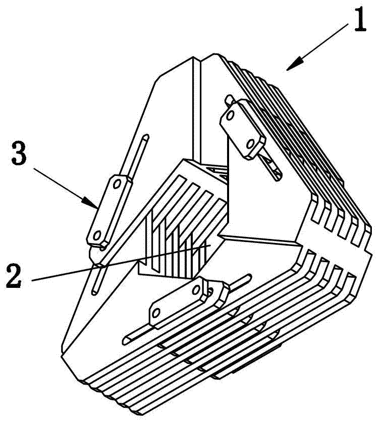
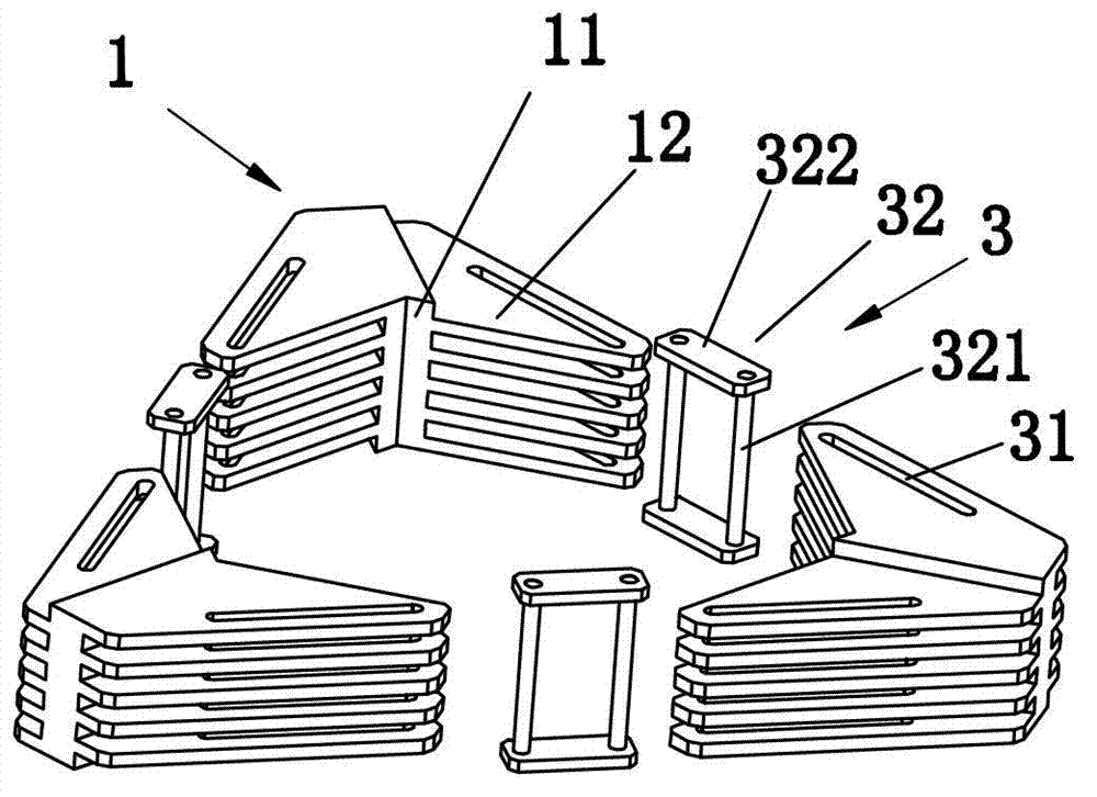
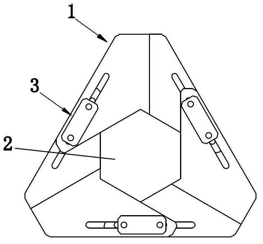
[0038] Embodiment one: if Figure 1-5 As shown, the present embodiment includes three clamping unit blocks 1, the clamping unit block 1 consists of a connecting portion 11, and comb-shaped connecting arms 12 fixed on both sides of the connecting portion 11, and the comb-like structure of the connecting arms 12 The upper row of combs is arranged along the axis of the scaling channel 2. The three clamping unit blocks 1 are sequentially connected by connecting arms 12 to form a closed ring structure. The center of the ring structure is a zoom channel 2, and two adjacent connecting arms 12 are staggered and interspersed to form a sliding fit. The row comb structure of the connecting arm 12 is a plurality of plate-like comb teeth 121 arranged in parallel, each comb tooth 121 is arranged axially along the zoom channel 2, then, that is, the side of the clamp unit block 1 facing the zoom channel 2 It is the gap between adjacent comb teeth 121 arranged in parallel, and the gap can ens...

Embodiment 2

[0044] Embodiment two: if Figure 6-8 As shown, the present embodiment includes two clamping unit blocks 1a, the clamping unit block 1a is composed of a connecting portion 11a, and a row of comb-shaped connecting arms 12a fixed on both sides of the connecting portion 11a, and a row of comb-like structures of the connecting arms 12a The upper row of combs is arranged along the axial direction of the zoom channel 2a. The two clamping unit blocks 1a are sequentially connected by connecting arms 12a to form a closed ring structure. The center of the ring structure is a zoom channel 2a, and two adjacent connecting arms 12a are staggered and interspersed to form a sliding fit.

[0045] In order to realize the motion control of the clamping unit block 1a, a guide structure 3a is provided between two adjacent connecting arms, and the guiding structure 3a guides the clamping unit block 1a to converge towards the center of the zoom channel 2a. There are a total of two guide structures ...

Embodiment 3

[0048] Embodiment three: as Figure 9-11 As shown, the present embodiment includes four clamping unit blocks 1b, the clamping unit block 1b consists of a connecting portion 11b, and comb-shaped connecting arms 12b fixed on both sides of the connecting portion 11b, and the comb-like structure of connecting arms 12b The upper row of combs is arranged along the axial direction of the zoom channel 2b. The four clamping unit blocks 1b are sequentially connected by connecting arms 12b to form a closed ring structure. The center of the ring structure is a scaling channel 2b, and two adjacent connecting arms 12b are staggered and interspersed to form a sliding fit.

[0049] In order to realize the motion control of the clamping unit block 1b, a guide structure 3b is provided between two adjacent connecting arms, and the guiding structure 3b can guide the clamping unit block 1b to converge toward the center of the zoom channel 2b. There are four guide structures 3b in total, and each ...


PUM


Abstract

The invention discloses a compression device for an artificial valve replacement device. The compression device comprises at least two clamp unit blocks; and the clamp unit blocks are inserted in a staggered way and are connected with each other in sequence through a comb structure and enclose a scaling channel. The compression device further comprises a guide structure for leading all the clamp unit blocks to fold towards the center of the scaling channel. According to the invention, when the artificial valve replacement device is placed in the scaling channel, the inner wall of the scaling channel props against the peripheral wall of the artificial valve replacement device; and when the clamp unit blocks are folded towards the center of the scaling channel under the action of outside force, the inner wall of the scaling channel simultaneously applies the force directing to the central direction of the scaling channel onto the peripheral wall of the artificial valve replacement device. The compression device has the beneficial effects that the manufacturing cost is low, the cleaning is convenient due to simple structure, and the requirements for operation sanitation during use can be completely satisfied, therefore, the production and maintenance costs are reduced, and the expense shifted to consumers is reduced.

Description

technical field [0001] The invention relates to a compression device, in particular to a compression device of an artificial valve replacement device. Background technique [0002] When the patient's own heart valve is mutated due to congenital or acquired diseases, causing the valve to fail to open and close normally, it will affect healthy life and even life. The variation of the heart valve can be divided into insufficiency and insufficiency, both of which can cause increased heart load. Whether the heart can still work normally under this load is the main basis for deciding whether the human heart valve should be replaced. And when the patient needs to change the valve, the existing method is to adopt surgical operation to change the valve. The doctor will open the chest for the patient and stop the heart, and connect it to the extracorporeal cardiopulmonary circulation system. Then open the patient's heart to remove the diseased heart valve, then suture the artificial ...

Claims


Application Information

Patent Timeline
Patent Type & Authority Applications(China)
IPC IPC(8): A61F2/24
CPCA61F2/2427A61F2/9522Y10T29/53657
Inventor 雷荣军訾振军
Owner VENUS MEDTECH (HANGZHOU) INC
Why Eureka
Try Eureka