Energy recovery method and device used for drying system

An energy recovery device and drying system technology, applied in drying, dryer, separation method and other directions, can solve the problems of low energy recovery efficiency of drying system, and achieve non-volatile, low solute saturated vapor pressure and chemical stability Good results

Active Publication Date: 2012-12-05
ZHEJIANG UNIV
View PDF8 Cites 10 Cited by
  • Summary
  • Abstract
  • Description
  • Claims
  • Application Information

AI Technical Summary

Problems solved by technology

[0005] The invention provides an energy recovery method and device for a drying system, which solves the problem of low energy recovery efficiency of the drying system

Method used


Image

  • Energy recovery method and device used for drying system
  • Energy recovery method and device used for drying system
  • Energy recovery method and device used for drying system

Examples


Embodiment 1~30

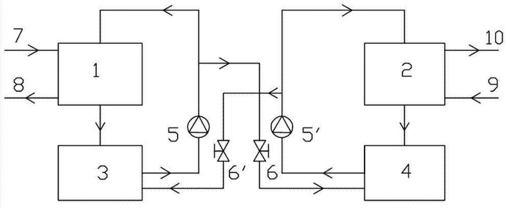
[0065] The energy recovery device that is used for drying system in the embodiment 1~30, such as figure 1 As shown, the device includes an absorption subsystem for drying exhaust gas dehumidification and a regeneration subsystem for regeneration of liquid hygroscopic agents;

[0066] The absorption subsystem includes a dehumidifier 1, a dehumidification solution pool 3, a first solution pump 5 and a first regulating valve 6; the dehumidifier 1 is provided with an exhaust gas inlet connected to the drying exhaust gas inlet pipe 7 and a drying The exhaust gas outlet connected to the exhaust gas outlet pipe 8; the solution outlet of the dehumidifier 1 is connected to the first inlet of the dehumidification solution pool 3, the outlet of the dehumidification solution pool 3 is connected to the inlet of the first solution pump 5, and the outlet of the first solution pump 5 is divided into two ways: One path is connected to the solution inlet of the dehumidifier 1, and the other pat...

Embodiment 31

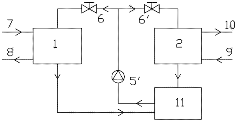
[0083] Energy recovery units for drying systems such as figure 2 As shown, the device includes an absorption subsystem for drying exhaust gas dehumidification and a regeneration subsystem for regeneration of liquid hygroscopic agents;

[0084] The absorption subsystem includes a dehumidifier 1 and a first regulating valve 6; the dehumidifier 1 is provided with a waste gas inlet connected to the drying waste gas inlet pipe 7 and a waste gas outlet connected to the drying waste gas outlet pipe 8; dehumidification The solution inlet of device 1 is connected with the outlet of first regulating valve 6;

[0085] The regeneration subsystem includes a regenerator 2, a solution pool 11, a second solution pump 5' and a second regulating valve 6'; the regenerator 2 is provided with an air inlet connected to the fresh air inlet pipe 9 and an air outlet connected to the air The air outlet connected to the pipeline 10; the solution inlet of the regenerator 2 is connected with the outlet ...

Embodiment 32

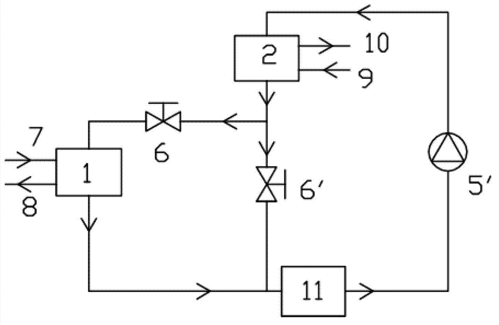
[0095] Energy recovery units for drying systems such as image 3 As shown, the device includes an absorption subsystem for drying exhaust gas dehumidification and a regeneration subsystem for regeneration of liquid hygroscopic agents;

[0096] The absorption subsystem includes a dehumidifier 1 and a first regulating valve 6; the dehumidifier 1 is provided with a waste gas inlet connected to the drying waste gas inlet pipe 7 and a waste gas outlet connected to the drying waste gas outlet pipe 8; dehumidification The solution inlet of device 1 is connected with the outlet of first regulating valve 6;

[0097] The regeneration subsystem includes a regenerator 2, a solution pool 11, a second solution pump 5' and a second regulating valve 6'; the regenerator 2 is provided with an air inlet connected to the fresh air inlet pipe 9 and an air outlet connected to the air The air outlet where the pipeline 10 is connected; the outlet of the second regulating valve 6' is connected with t...


PUM


Abstract

The invention discloses an energy recovery method and an energy recovery device used for a drying system. The energy recovery method used for the drying system includes the following steps: after exhaust gas which needs drying is dehumidified by liquid moisture absorbent, the separated dried exhaust gas which needs drying is heated by the liquid moisture absorbent which absorbs the moistures and returns to the drying system; and the liquid moisture absorbent which absorbs the moistures and releases heat is regenerated through fresh air to be reused for dehumidification. In such a way, the liquid moisture absorbent is recycled. The invention further provides the energy recovery device used for the drying system. The energy recovery method disclosed by the invention can simultaneously recover the latent heat and the sensible heat in the exhaust gas which needs drying, and has a remarkable energy-saving effect, the utilization efficiency of the drying heat is improved. The energy recovery device is simple in structure and convenient to operate.

Description

technical field [0001] The invention belongs to the field of energy recovery, and in particular relates to an energy recovery method and device for a drying system. Background technique [0002] The drying process is widely used in industries such as wood, paper, grain, medicinal materials, printing and dyeing, and other industries. The usual method of drying process is to pass the hot air with low humidity into the dryer, directly contact with the material to be dried, so that the temperature rises, the moisture is vaporized and separated from the material, and is discharged out of the drying system with the airflow. The exhaust air flow is called dry exhaust air. The drying exhaust gas has a high temperature and contains a large amount of water vapor, which takes away 40% to 70% of the heat energy of the drying system, and the heat energy is seriously wasted. This part of the heat energy lost with the exhaust gas becomes the exhaust heat loss. The exhaust heat loss of th...

Claims


Application Information

Patent Timeline
Patent Type & Authority Applications(China)
IPC IPC(8): F26B21/02B01D53/26
CPCY02P70/10
Inventor 陈光明叶碧翠郑皎
Owner ZHEJIANG UNIV
Why Eureka
Try Eureka