
Phase correction method for arbitrary impulse converter transformer current difference

A phase correction, current differential technology, applied in the phase angle between voltage and current, conversion equipment that can be converted to DC without intermediate conversion, DC network circuit devices, etc. T3 three-phase differential current, differential protection same-name phase current phase correction, etc.

Inactive Publication Date: 2012-12-05
EXAMING & EXPERIMENTAL CENT OF ULTRAHIGH VOLTAGE POWER TRANSMISSION COMPANY CHINA SOUTHEN POWER GRID
View PDF2 Cites 8 Cited by
  • Summary
  • Abstract
  • Description
  • Claims
  • Application Information

AI Technical Summary

Problems solved by technology

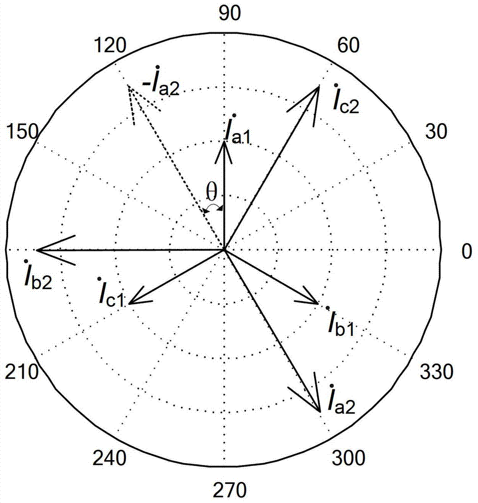
At this time, the differential protection of the converter transformers T2 and T4 can still be realized by the formula (3), but the differential protection between the converter transformers T1 and T3 cannot use the above formula to realize the phase correction of the phase current of the same name, so it is impossible to calculate the The three-phase differential current of T1 and T3, that is, the current phase correction method is only applicable to the case where the phase difference of the phase current of the same name on both sides of the converter transformer is 30N (N is an integer)

Method used


Image

  • Phase correction method for arbitrary impulse converter transformer current difference
  • Phase correction method for arbitrary impulse converter transformer current difference
  • Phase correction method for arbitrary impulse converter transformer current difference

Examples


Embodiment Construction

[0059] Below in conjunction with embodiment and accompanying drawing, the present invention is described in detail, and following description starts with Figure 5 as an example.

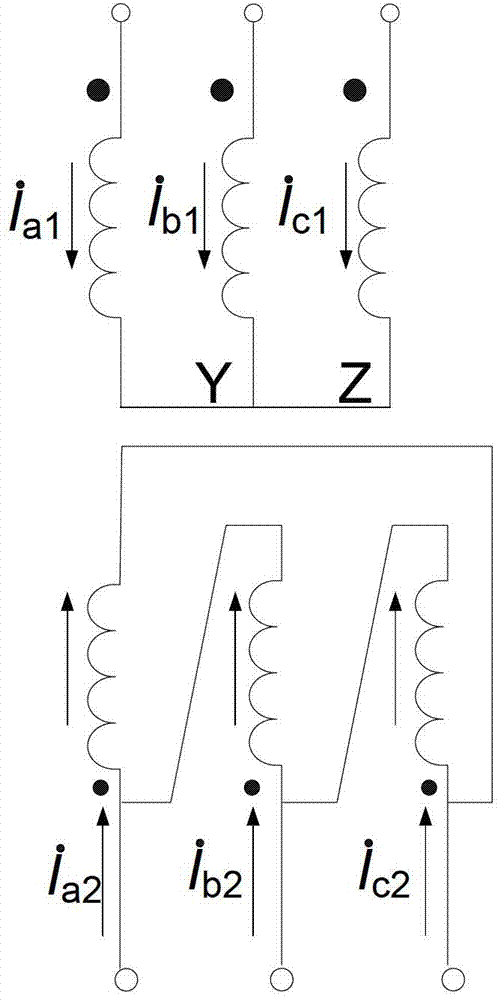
[0060] Figures 5 to 9 middle, Figure 5 is the wiring diagram of the 24-pulse converter transformer, assuming that the phase difference θ between the positive sequence currents of the T1 converter transformer is any angle, that is, I a1 Advance-I a2 When θ is any angle, such as Image 6 shown. Then the phase relationship among the positive sequence, negative sequence and zero sequence of phase A on the valve side of the converter is as follows: Figure 7 , Figure 8 , Figure 9 shown.

[0061] I ps_1 , I ns_1 , I zs_1 are the positive sequence, negative sequence and zero sequence components of the three-phase current of the current transformer on the side of the T1 converter transformer network, I ps_2 , I ns_2 , I zs_2 are respectively the positive sequence, negative sequence and zer...


PUM


Abstract

The invention relates to a phase correction method for arbitrary impulse converter transformer current difference. When a converter transformer is at a no-load status, a phase difference theta exists in positive sequence current of a line side winding and a valve side winding, and the theta is any angle. The phase correction method comprises the following steps: selecting a side winding of the converter transformer as a reference winding, and performing phase correction to the other side winding current towards the reference winding current; using a phase relationship of three-phase current sequence components on the two sides of the converter transformer, and a conversion method of the sequence components and the phase components to calculate differential current. Due to the adoption of the phase correction method, the differential current of any impulse converter transformer can be calculated, so that a high-voltage direct-current power transmission system safely and stably operates for a long time; the method has the advantages of easily applying and preventing the generation of false differential current. Moreover, according to the phase correction method, a problem that the phase correction is only achieved when the same-phase current phase difference on the two sides of the converter transformer is 30 N (N is an integral number) as the current phase correction method adopts the adding and subtracting of the three-phase current vectors on certain side can be solved.

Description

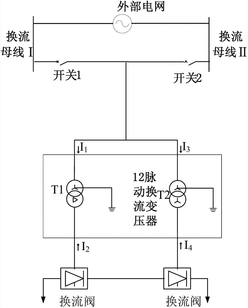
technical field [0001] The invention belongs to the technical field of power systems, and in particular relates to a phase correction method when the phase difference of the phase currents of the same name on both sides of a converter transformer is at any angle. Background technique [0002] Due to its unique advantages, such as: long distance, high power, asynchronous networking, fast power adjustment, power flow controllability, transmission economy, etc., HVDC transmission is more and more widely used. In order to reduce the harmonic components of the system, different connection methods of transformer windings are used. At present, most high-voltage DC projects use 12-pulse valve group connection methods, such as figure 1 As shown, it provides two sets of three-phase symmetrical commutation voltages with equal amplitudes and a phase difference of 30° (fundamental electrical angle) for the two transformers connected in series, so as to realize twelve-pulse commutation. ...

Claims


Application Information

Patent Timeline
Patent Type & Authority Applications(China)
IPC IPC(8): H02J1/00G01R25/00H02M5/10
Inventor 田庆
Owner EXAMING & EXPERIMENTAL CENT OF ULTRAHIGH VOLTAGE POWER TRANSMISSION COMPANY CHINA SOUTHEN POWER GRID
Learn More