Method and device for digital filtering
A digital filtering and filter technology, applied in the field of digital filtering methods and devices, can solve problems such as a large number of multipliers, and achieve the effects of improving operating efficiency, occupying less hardware resources, and efficient FIR filtering calculation.
- Summary
- Abstract
- Description
- Claims
- Application Information
AI Technical Summary
Problems solved by technology
Method used
Image
Examples
Embodiment 1
[0031] The impulse response generated by the unit step signal u(n) passing through the FIR filter system is the unit step response s(n), and its expression is: where h(i) is the single impulse response of the FIR filter. When the input signal x(n) is a rectangular wave or a step wave, its time-domain waveform changes slowly and maintains a constant level most of the time, we can according to the transition edge of the input signal (for example, at t 1 ~t k There are k jumps in total, k≥1) Decompose the input signal into the sum of multiple step signals: where A k is t k The amplitude of the step signal at each moment. Since the FIR filter is a linear time-invariant system, according to the superposition theorem:
[0032] y ( n ) = Σ i = 0 L - 1 h ...
Embodiment 2
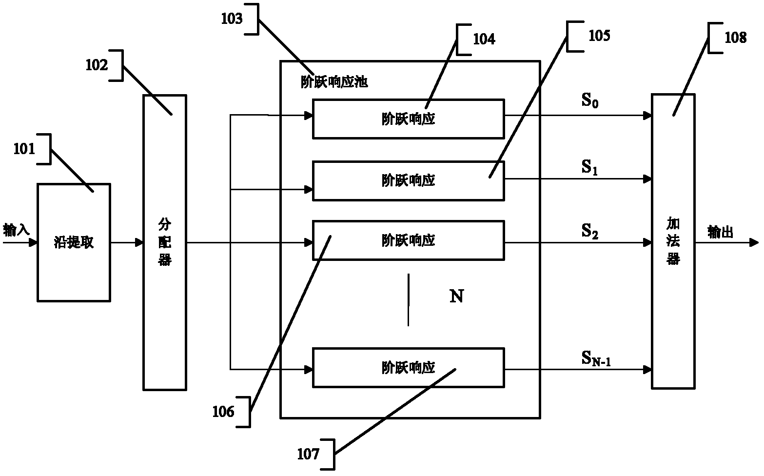
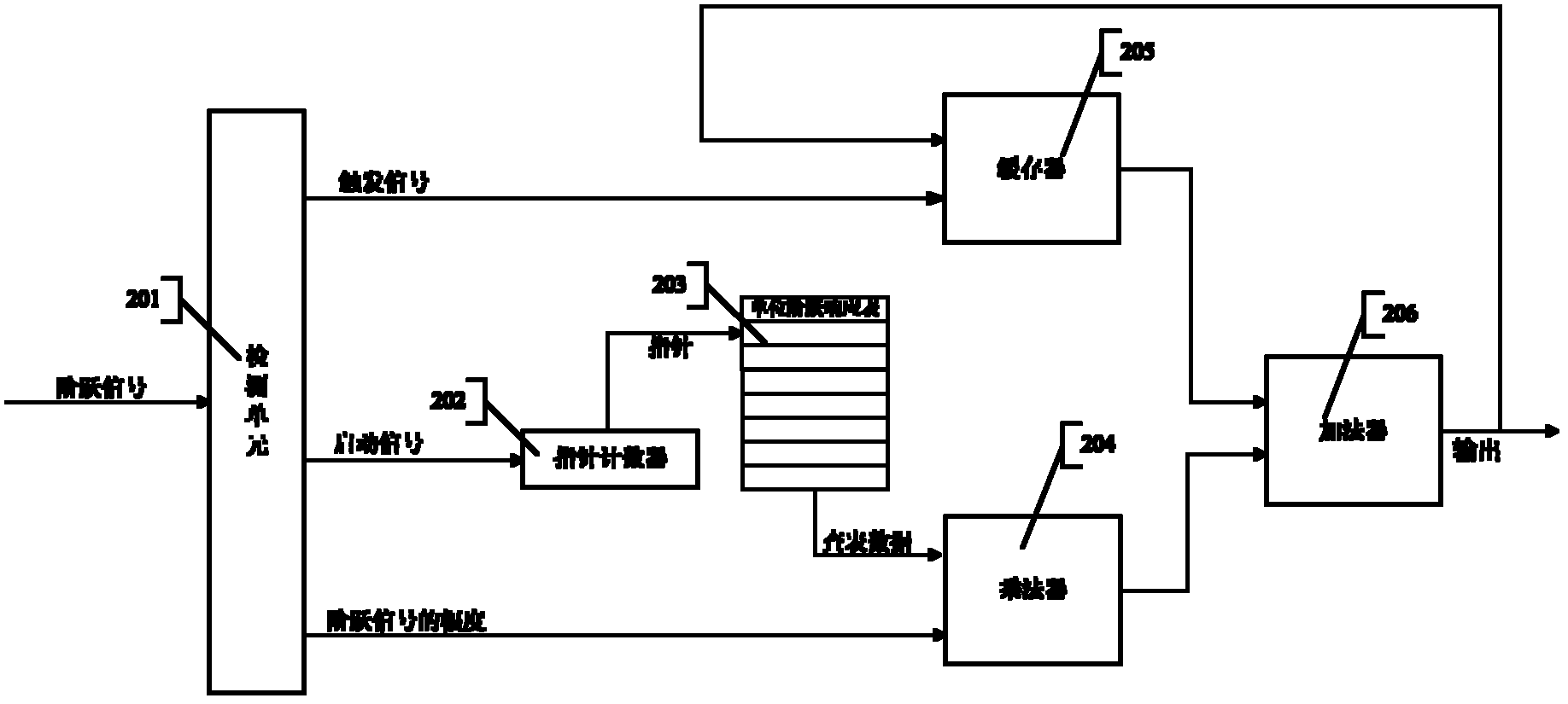
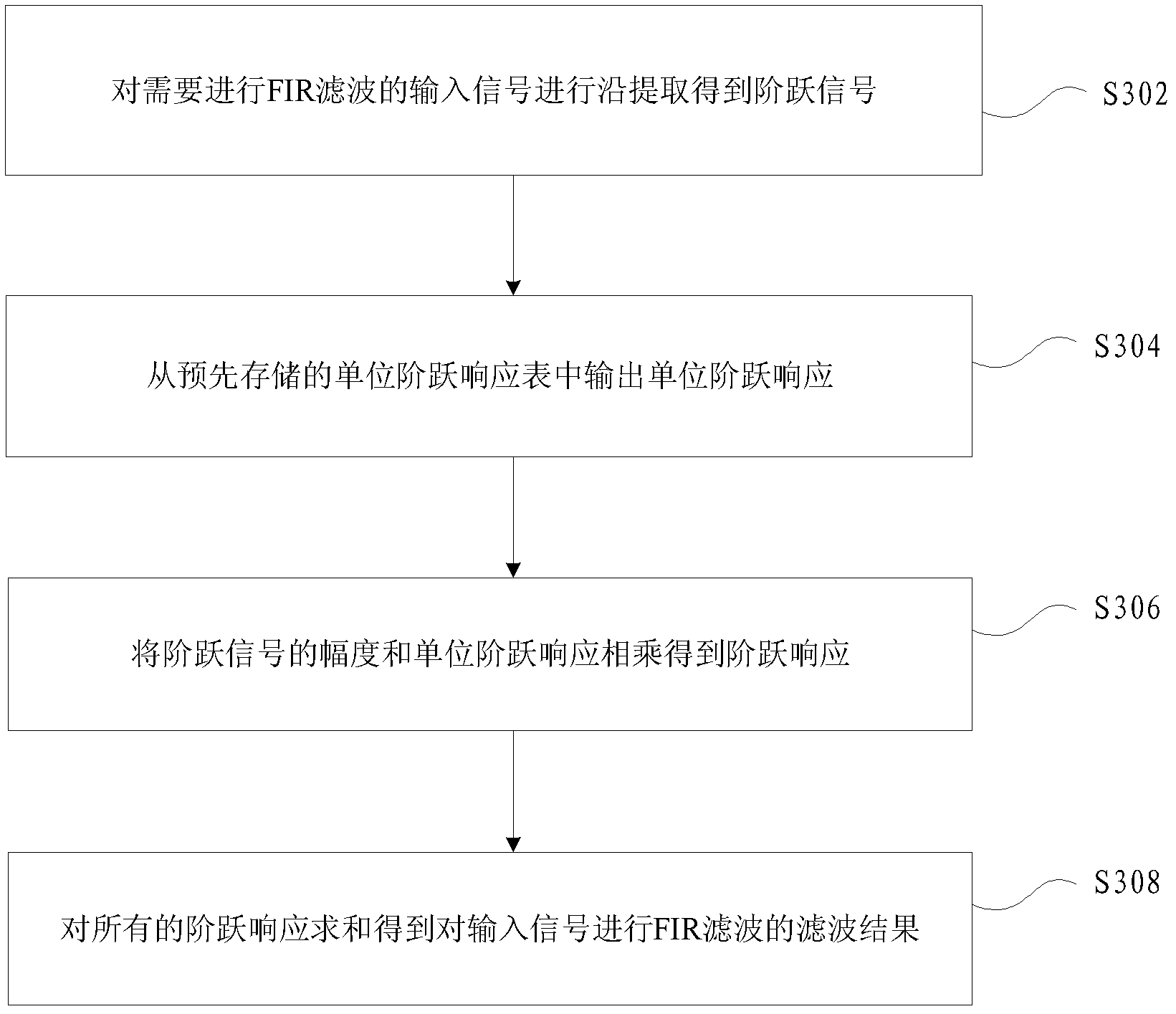
[0047] based on figure 1 and figure 2 As shown in the filtering device, the present invention also provides a preferred digital filtering method, such as image 3 As shown, it includes the following steps:
[0048] S302, performing edge extraction on the input signal requiring FIR filtering to obtain a step signal;
[0049] S304, output the unit step response from the pre-stored unit step response table;
[0050] S306, multiplying the amplitude of the step signal by the unit step response to obtain the step response;
[0051] S308, summing up all the step responses to obtain a filtering result of performing FIR filtering on the input signal.
[0052] In this preferred embodiment, by extracting the step signal, looking up the table to output the step response, and superimposing the step response, the efficient FIR filter calculation is realized. The hardware structure corresponding to this method is simple and takes up hardware The resources are very few, and the problem ...
Embodiment 3
[0059] Below in conjunction with accompanying drawing and specific embodiment, two embodiments of the present invention are described in further detail again:
[0060] The first embodiment is to design a 649-order low-pass FIR filter, Figure 4 is the single impulse response curve of the FIR filter, Figure 5 is the unit step response of the FIR filter, Figure 6 Is the input signal, its waveform is a step wave, the maximum number of changes that occur within the unit step response length of the filter is 3, and N is not less than 3. Preferably, N takes a value of 3 in this example, and the step response pool There are 3 step response modules.
[0061] S1: Calculate the unit step response of the 649-order low-pass FIR filter, and store the unit step response data in a table. Figure 5 is the unit step response curve of the filter.
[0062] S2: Perform edge extraction on the input signal in the edge extraction module to obtain multi-channel step signals. Figure 7 Among th...
PUM
 Abstract
Description
Claims
Application Information
 - R&D
- Intellectual Property
- Life Sciences
- Materials
- Tech Scout
- Unparalleled Data Quality
- Higher Quality Content
- 60% Fewer Hallucinations
Browse by: Latest US Patents, China's latest patents, Technical Efficacy Thesaurus, Application Domain, Technology Topic, Popular Technical Reports.
© 2025 PatSnap. All rights reserved.Legal|Privacy policy|Modern Slavery Act Transparency Statement|Sitemap|About US| Contact US: help@patsnap.com


