Wick structure for vapor chamber

A liquid-absorbing core and soaking plate technology, which is applied in indirect heat exchangers, lighting and heating equipment, cooling/ventilation/heating transformation, etc., can solve the problems of large flow resistance, small capillary pressure, high capillary pressure, etc., to achieve Improve heat dissipation efficiency, increase capillary suction, and reduce flow resistance

Active Publication Date: 2012-12-05
SOUTH CHINA UNIV OF TECH
View PDF7 Cites 20 Cited by
  • Summary
  • Abstract
  • Description
  • Claims
  • Application Information

AI Technical Summary

Problems solved by technology

[0004] 1. Powder sintering and screen sintering liquid-absorbing cores have small capillary pore radius and high capillary pressure, so the flow resistance is large, the permeability is small, and the heat dissipation efficiency is not high.
[0005] 2. The channel-type liquid-absorbing core has high permeability, but the capillary pressure is small, which cannot provide enough reflux power for the working fluid, which will reduce the heat dissipation efficiency of the vapor chamber
[0006] 3. As the channel type liquid-absorbing core is set independently and parallel to each other, local high temperature will be caused after partial blockage, and the temperature uniformity performance is poor

Method used


Image

  • Wick structure for vapor chamber
  • Wick structure for vapor chamber
  • Wick structure for vapor chamber

Examples


Embodiment 1

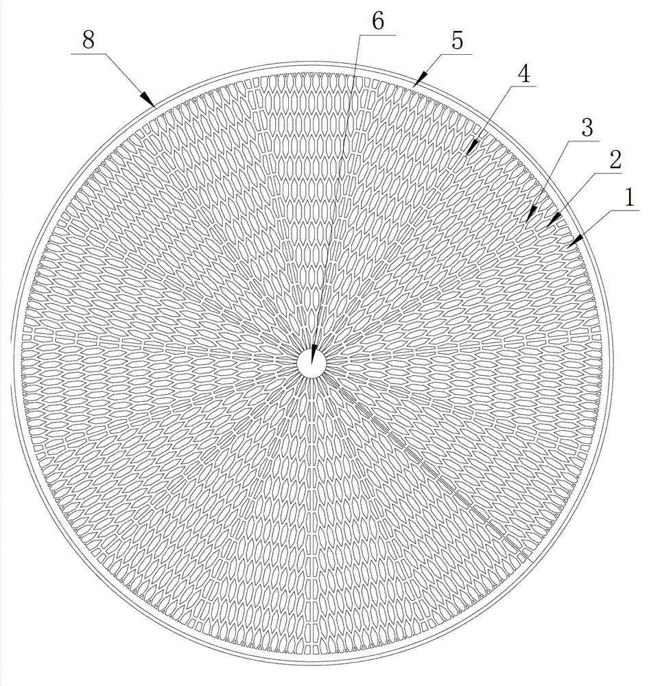
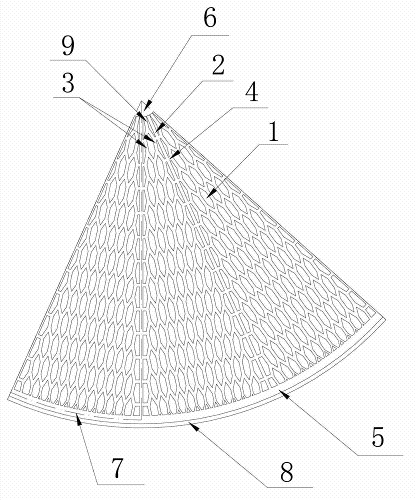
[0038] see Figure 1 ~ Figure 4 The liquid-absorbing core structure of the vapor chamber of this embodiment is arranged on a disc-shaped vapor chamber shell 8 made of copper. The fan-shaped condensation zone 7. Each condensing zone 7 is composed of a 12-level channel structure formed by branching outwards from the starting channel 9 at the center. Among them, the starting channel 9 is zero-level, and the zero-level bifurcation point I is divided into two, so that the first level has two thin channels 3, and the angle between the two bifurcated thin channels 3 is 45° , that is, the bifurcation angle θ 1 is 45°, and the two bifurcated thin channels 3 are bent into a parallel state and extend outward; the bifurcation points II of the two thin channels 3 of the first stage are divided into two, and the bifurcation angle θ 2 It is also 45°. Among the four bifurcated thin channels 3, the two in the middle intersect and merge into one, so that the second stage has three thin chann...

Embodiment 2

[0046] see Figure 7 , in this embodiment, each condensation zone 7 is divided into a multi-stage channel structure from the center to the outside, and the stages are separated by concentric arc-shaped channels 11, and the first stage is formed by bifurcating the starting channel 9 Two thin channels 3 are formed, and the bifurcation angle θ is 60°; the two thin channels 3 of the first stage extend outward and intersect with the arc-shaped channel 11 between the first stage and the second stage, and at each intersection point It is bifurcated into two thin channels 3 to form the second stage, and the bifurcation angle β is 50°; the thin channel 3 of the second stage extends outward and connects with the arc-shaped channel 11 between the second stage and the third stage Intersect, and each intersection bifurcates into two thin channels 3, forming the third level, the bifurcation angle γ is 40°; the third level of thin channels 3 extends outward and connects with the The arc-sha...

Embodiment 3

[0050] see Figure 8 , the difference between the network channel structure of this embodiment and Embodiment 1 is that in this embodiment, the four thin channels 3 separated from two adjacent thin channels 3 at the same level do not intersect, and the two in the middle The thin channels 3 communicate with each other through horizontal channels 12 , and the thin channels 3 and the horizontal channels 12 of the above-mentioned levels communicate with each other to form a network channel structure.

[0051] In this embodiment, the bifurcation angles θ of the narrow channels 3 at all levels are 45°, the ratio of the width of the narrow channels 3 of the latter stage to the width of the narrow channels 3 of the previous stage is 0.8, and the fine grooves of the latter stage The ratio of the length of the track 3 to the length of the previous fine channel 3 is 0.8.

[0052] Embodiments other than the above in this embodiment are the same as in Embodiment 1.

[0053] The above is ...


PUM


Abstract

The invention discloses a wick structure for a vapor chamber. The wick structure comprises multiple condensing zones radiating from center to outside, each condensing zone is formed by a multistage channel structure formed by branching step-by-step from a central beginning channel to outside, each stage comprises at least two narrow channels, the number of the narrow channels in each stage increases from center to outside stage-by-stage, the narrow channels in each stage and the narrow channels among stages are mutually communicated to enable each condensing zone to form a latticed channel structure, the width of the narrow channels of a next stage is smaller than that of the narrow channels of a front stage, and the length of the narrow channels of a next stage is smaller than or equal to that of the narrow channels of a front stage. The wick structure for the vapor chamber has the advantages of high capillary attraction, low flow resistance and high temperature evenness and heat radiating efficiency.

Description

technical field [0001] The invention relates to a soaking plate, in particular to a liquid-absorbing core structure of the soaking plate. Background technique [0002] With the continuous advancement of high-performance electronic technology, practical applications require high-speed operation of electronic devices and miniaturization of structural dimensions. While the operation of electronic devices is speeding up and the structure scale is miniaturized, highly integrated electronic devices will inevitably lead to higher heat flux density. Therefore, the problem of heat dissipation has become a bottleneck restricting the development of electronic technology. [0003] At present, the vapor chamber has been widely used as a high-efficiency heat dissipation device in the heat dissipation of electronic devices. Compared with the traditional heat dissipation technology, the vapor chamber has high heat dissipation efficiency and good temperature uniformity. Vapor chamber mainl...

Claims


Application Information

Patent Timeline
Patent Type & Authority Applications(China)
IPC IPC(8): H05K7/20F28D15/02
CPCH01L23/473
Inventor 刘旺玉彭毅田玉福
Owner SOUTH CHINA UNIV OF TECH
Why Eureka
Try Eureka