Compound molding tool system for hot stretch bending and creep deformation of section bar and application method of compound molding tool system

A composite forming and heating system technology, applied in the field of metal thermal processing, can solve problems such as many processes, poor forming precision, and difficulty in achieving precise forming, and achieve the effects of reducing manufacturing costs, improving forming precision and quality, and reducing springback

Inactive Publication Date: 2012-12-12
BEIHANG UNIV
View PDF15 Cites 22 Cited by
  • Summary
  • Abstract
  • Description
  • Claims
  • Application Information

AI Technical Summary

Problems solved by technology

[0004] The traditional profile stretch bending process has shortcomings such as the need for multiple sets of tooling, long working hours, and large springback. For example, in the secondary room temperature stretch bending heating correction method for plate bending profiles, the thinning and thickness uniformity of the profile are difficult to control. Requires multiple sets of tooling (stamping upper and lower dies, stretch bending dies, shape-calibration tooling), high cost of tooling; requires multiple processes (hot stamping, two room temperature stretch bending, thermal shape correction), long production cycle, and high cost of working hours
The heat-incremental bending forming heating and shaping process requires repeated heating, and the existence of a large number of stress gradients makes it very di

Method used


Image

  • Compound molding tool system for hot stretch bending and creep deformation of section bar and application method of compound molding tool system
  • Compound molding tool system for hot stretch bending and creep deformation of section bar and application method of compound molding tool system
  • Compound molding tool system for hot stretch bending and creep deformation of section bar and application method of compound molding tool system

Examples


Embodiment Construction

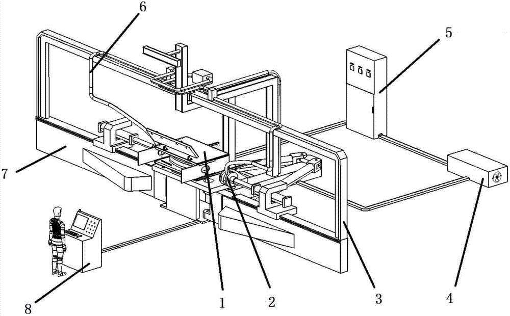
[0043] 1) A thermal stretch bending and creep composite forming tooling system for profiles according to the present invention includes a stretch arm type profile stretch bending machine 7, a heating box 1, a self-resistance heating system, an electrical control cabinet 8 and clamps 2, such as figure 1 shown. The position connection relationship between them is: the heating box 1 is located on the working table in the middle of the stretch arm type profile bending machine 7, and the electrical control cabinet 8 is located in front of the stretch arm type profile stretch bending machine 7 and connected with the stretch arm type profile stretch bending machine 7 connections, the self-resistance heating system is located on the periphery of the system, and the clamp 2 is installed on the stretching arm of the stretching arm type profile stretch bending machine 7.

[0044] The stretch arm type profile stretch bending machine 7 is a common profile stretch bending forming equipment,...


PUM


Abstract

The invention relates to a compound molding tool system for hot stretch bending and creep deformation of a section bar. The compound molding tool system comprises a cantilever-type section bar stretch bender, a heating box, a self-resistance heating system, an electric control cabinet and a clamp, wherein the heating box is located on the working table of the middle part of the cantilever-type section bar stretch bender; the electric control cabinet is located in front of the cantilever-type section bar stretch bender and is connected with the cantilever-type section bar stretch bender; the self-resistance heating system is located at the periphery of the tool system; and the clamp is arranged on a cantilever of the cantilever-type section bar stretch bender. An application method of the compound molding tool system for the hot stretch bending and the creep deformation of the section bar comprises six steps. According to the compound molding tool system for the hot stretch bending and the creep deformation of the section bar, the hot stretch bending process of the creep deformation process of the section bar are compounded; the plastic deformation resistance of the section bar is reduced; and the residual stress after the section bar is processed is reduced, and thereby, resilience is reduced, and the molding precision and the structure stability are improved. Compared with products obtained by adopting a traditional stretch bending method, a final product obtained by the compound molding tool system is higher in quality, and the production efficiency is increased.

Description

technical field [0001] The invention relates to a profile hot stretch bending creep composite forming tooling system and a use method thereof, which are suitable for thermal forming of profiles such as titanium alloys and belong to the technical field of metal thermal processing. Background technique [0002] The profile stretch bending process has been widely used in the manufacture of aircraft and automobile profile bending parts. In aircraft manufacturing, the stretch bending process is mainly used to form skeleton parts such as fuselage, wing, air intake frame, purlin, reinforcing edge; in automobile production, it is mainly used to form hollow profiles of body structure and bumper bending parts, etc. [0003] With the requirements of stealth, high maneuverability and high reliability of the new generation of aircraft, the application of high-strength and lightweight materials such as titanium alloys is increasing, and the requirements for product processing accuracy ar...

Claims


Application Information

Patent Timeline
IPC IPC(8): B21D7/16
CPCB21D11/02
Inventor 李东升邓同生李小强
Owner BEIHANG UNIV
Why Eureka
Try Eureka