Bellows-type piezoelectrically-hydraulically-actuated microfluidic servo valve and actuating device thereof

A bellows type, microfluidic technology, applied in valve devices, valve operation/release devices, valve details, etc., can solve the problems of unstable hydraulic magnification and poor sealing reliability, and achieve good elasticity and good sealing. performance effect

Inactive Publication Date: 2012-12-12
HARBIN INST OF TECH
View PDF4 Cites 4 Cited by
  • Summary
  • Abstract
  • Description
  • Claims
  • Application Information

AI Technical Summary

Problems solved by technology

[0003] The purpose of the present invention is to solve the problem of poor sealing reliability and unstable magnification of the hydraulic amplifier in the existing microfluidic technology in which the piezoelectric drive is used in conjunction with the hydraulic amplifier, and provides a bellows piezoelectric hydraulic actuator. Dynamic microfluidic servo valve and its driving device

Method used


Image

  • Bellows-type piezoelectrically-hydraulically-actuated microfluidic servo valve and actuating device thereof
  • Bellows-type piezoelectrically-hydraulically-actuated microfluidic servo valve and actuating device thereof

Examples


specific Embodiment approach 1

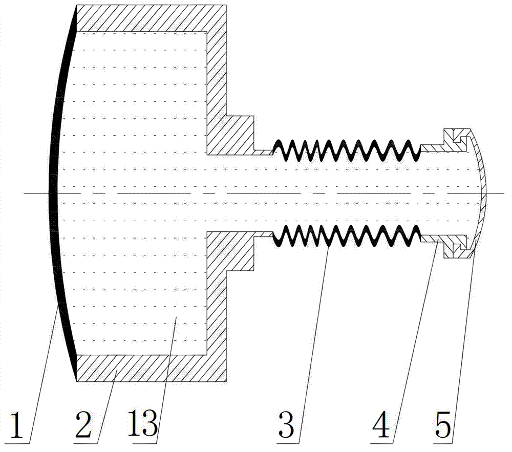
[0017] Specific implementation mode one: the following combination figure 1 Describe this embodiment, the bellows type piezoelectric fluid actuated microfluidic servo valve in this embodiment, it includes a piezoelectric diaphragm 1, it also includes a first chamber holder 2, a bellows 3, a second chamber Cavity cage 4 and elastic diaphragm 5,

[0018] The first chamber holder 2 is barrel-shaped, and the central bottom of the drum is provided with a through hole, which is the outlet of the first chamber holder 2; the second chamber holder 4 is cylindrical,

[0019] The piezoelectric diaphragm 1 is covered and fixed on the first cavity holder 2, and the outlet side of the first cavity holder 2 and the inlet side of the second cavity holder 4 realize sealed communication through the bellows 3, and the elastic diaphragm 5 is covered and fixed on the outlet side of the second cavity holder 4,

[0020] The piezoelectric membrane 1 , the first cavity holder 2 , the bellows 3 , the...

specific Embodiment approach 2

[0023] Specific implementation mode two: the following combination figure 1 This embodiment is described. This embodiment is a further description of Embodiment 1. The inner diameter of the second cavity holder 4 is the same as the inner diameter of the through hole on the first cavity holder 2 .

specific Embodiment approach 3

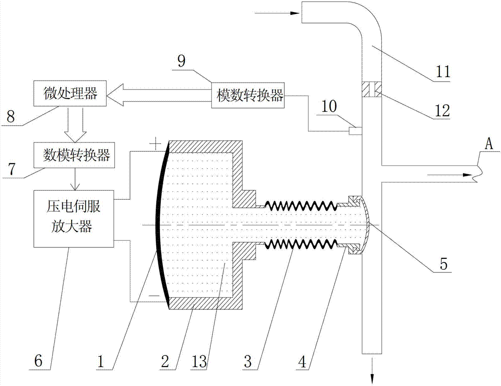
[0024] Specific implementation mode three: the following combination figure 2 Describe this embodiment, the bellows-type piezoelectric fluid-actuated microfluidic servo valve drive device described in Embodiment 1 of this embodiment, which includes a piezoelectric servo amplifier 6, a digital-to-analog converter 7, a microprocessor 8. Analog-to-digital converter 9 and pressure sensor 10,

[0025] The pressure sensor 10 is used to collect the pressure signal of the polydimethylsiloxane microfluidic channel under test, and the sampling signal output end of the pressure sensor 10 is connected to the sampling signal input end of the analog-to-digital converter 9, and the digital signal of the analog-to-digital converter 9 The output end is connected to the sampling signal input end of the microprocessor 8, the control signal output end of the microprocessor 8 is connected to the digital signal input end of the digital-to-analog converter 7, and the analog signal output end of the...


PUM


Abstract

The invention relates to a bellows-type piezoelectrically-hydraulically-actuated microfluidic servo valve and an actuating device thereof and belongs to the technical field of microfluidic control. The problems of poor sealing reliability and instability in amplification factors of hydraulic amplification by means of matching piezoelectric actuating with a hydraulic amplifier in existing microfluidics are solved. A first accommodating cavity retainer of the servo valve is in the shape of a drum, a through hole is arranged at the center bottom of the drum, a piezoelectric diaphragm covers and is fixed on the first accommodating cavity retainer, an outlet side of the first accommodating cavity retainer and an inlet side of a second accommodating cavity retainer are communicated in a sealing manner through a bellows, and an elastic diaphragm covers and is fixed on an outlet side of the second accommodating cavity retainer. The actuating device comprises a piezoelectric servo amplifier, a digital-to-analog converter, a microprocessor, an analog-to-digital converter and a pressure sensor. The bellows-type piezoelectrically-hydraulically-actuated microfluidic servo valve and the actuating device thereof are applicable to a piezoelectrically-hydraulically-actuated microfluidic system.

Description

technical field [0001] The invention relates to a bellows type piezoelectric liquid actuated microfluidic control servo valve and a driving device thereof, belonging to the technical field of microfluidic control. Background technique [0002] At present, micropumps and microvalves are the main control components and the most important components of microfluidic systems. The structure of microfluidic control servo valves plays an important role in the performance of microfluidic systems. As an important microfluidic control component, microfluidic control servo valve can realize high-precision microfluidic flow control. Although the existing microfluidic servo microvalve has the advantages of high precision, less heat generation, and faster response speed, it has disadvantages such as high driving voltage, small output force, small motion range, or poor dynamic response. Therefore, it is necessary to develop a A new type of microfluidic servo valve with good overall perform...

Claims


Application Information

Patent Timeline
Patent Type & Authority Applications(China)
IPC IPC(8): F16K99/00F16K31/126F16K31/02
Inventor 李松晶曾文佟志忠刘旭玲
Owner HARBIN INST OF TECH
Why Eureka
Try Eureka