Wide-band low-temperature radio-frequency microwave power amplitude limiter with extremely-low insertion loss

A microwave power and limiter technology, which is applied in the direction of limiting the amplitude with diodes, can solve problems such as unstable work, large system noise, and poor matching performance, and achieve the effect of preventing burning

Inactive Publication Date: 2012-12-12
视拓超导科技有限公司
View PDF2 Cites 10 Cited by
  • Summary
  • Abstract
  • Description
  • Claims
  • Application Information

AI Technical Summary

Problems solved by technology

[0005] (1) Since the minimum operating temperature of the components used in the conventional RF microwave limiter is 250K, it cannot work stably at a low temperature of 75K;
[0006] (2) Due to the unidirectional conductivity of the limiting diode, the limiting circuit can only limit the input power signal of the positive half cycle
[0007] (3) Due to the parasitic effect of the radio frequency inductance, the matching performance of the limiter becomes worse with the increase of the frequency, which is manifested by the deterioration of the standing wave ratio and the increase of the insertion loss of the limiter, which brings a greater impact on the system. noise
[0008] (4) Since the conventional radio frequency microwave limiter only uses a single pin two limiting transistor, the isolation of the circuit is small, and the leakage level is high, which cannot effectively prevent the system from being burned by high-power signals

Method used


Image

  • Wide-band low-temperature radio-frequency microwave power amplitude limiter with extremely-low insertion loss
  • Wide-band low-temperature radio-frequency microwave power amplitude limiter with extremely-low insertion loss
  • Wide-band low-temperature radio-frequency microwave power amplitude limiter with extremely-low insertion loss

Examples


Embodiment Construction

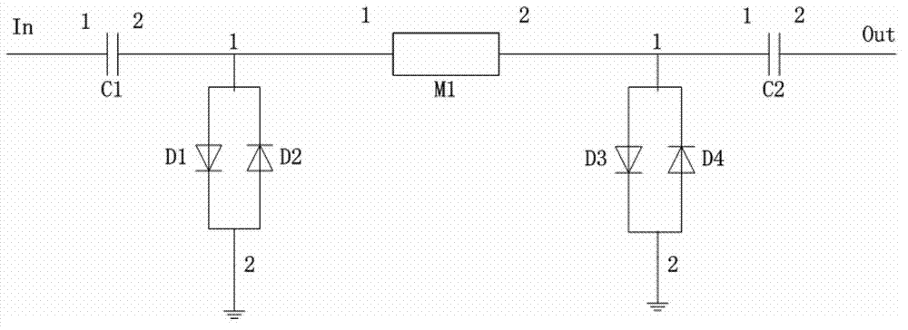
[0026] The specific embodiment of the present invention is described as follows in conjunction with accompanying drawing: A kind of broadband low-temperature radio frequency microwave power limiter with extremely low insertion loss that the present invention proposes, such as image 3 As shown, its features are: including four Pin limiting diodes D1, D2, D3, D4, two RF microwave DC blocking capacitors C1, C2, a quarter-wavelength microstrip line; 1 end of capacitor C1 is connected to RF Microwave input, the 2 terminals of capacitor C2 are connected to the output of radio frequency microwave; Pin limiting diodes D1 and D2, D3 and D4 are respectively reversed to form two sets of Pin limiting diode pairs; D1 and D2 form the first group of Pin limiting diodes Terminal 1 of the pair is connected to terminal 1 of the quarter-wavelength microstrip line and terminal 2 of capacitor C1, and terminal 2 of the first group of Pin limiting diode pairs is connected to ground; the second group...


PUM


Abstract

The invention relates to a wide-band low-temperature radio-frequency microwave power amplitude limiter with extremely-low insertion loss and belongs to the technical field of audio-frequency microwave power amplitude limiters. The amplitude limiter comprises four Pin amplitude-limiting diodes, two radio-frequency microwave blocking capacitors C1 and C2 and a quarter-wavelength micro-strip line, wherein the two capacitors are respectively connected with a radio-frequency microwave input-output end; the four Pin amplitude-limiting diodes are respectively connected inversely to form two groups of Pin amplitude-limiting diode pairs; the end I of the first group of Pin amplitude-limiting diode pair is connected with the end I of the quarter-wavelength micro-strip line and the end II of the capacitor C1, the end II of the Pin amplitude-limiting diode pair is connected with the ground; the end I of the second group of Pin amplitude-limiting diode pair is connected with the end II of the quarter-wavelength micro-strip line and the end I of the capacitor C2, and the end II of the Pin amplitude-limiting diode pair is connected with the ground. The amplitude limiter has an ultra-wide working band and extremely-low leakage potential, can be used for protecting a high-temperature super-conduction filter system working under a low-temperature vacuum environment from being burned out by strong signals.

Description

technical field [0001] The invention belongs to the technical field of radio-frequency microwave power limiter circuits, in particular to a wide-band low-temperature radio-frequency microwave power limiter with extremely low differential loss working in a low-temperature (75K) vacuum environment. Background technique [0002] High-temperature superconducting filter system is one of the important application fields of high-temperature superconducting microwave circuit design. The high temperature superconducting filter system has extremely low noise figure, high band edge steepness, and good out-of-band rejection. It can be applied to the receiver front end of various microwave communication equipment, which can greatly improve the sensitivity and selectivity of the entire system. Therefore, it has broad application prospects and huge market potential in microwave communication fields such as mobile communication, military communication, and satellite communication. High tem...

Claims


Application Information

Patent Timeline
Patent Type & Authority Applications(China)
IPC IPC(8): H03G11/02
Inventor 陈毅东曹必松魏斌张晓平马骁
Owner 视拓超导科技有限公司
Why Eureka
Try Eureka