Method for measuring absolute position of rotor in motor servo system

A servo system and absolute position technology, applied in the direction of measuring devices, instruments, etc., can solve the problems of no recovery ability, unable to give absolute zero position, etc., to improve cost performance, reduce signal processing circuits and coarse-fine coupling operations, and simplify machinery structure effect

Active Publication Date: 2012-12-19
BEIJING PULIMEN ELECTRO MECHANICAL HIGH TECHN CO
View PDF5 Cites 14 Cited by
  • Summary
  • Abstract
  • Description
  • Claims
  • Application Information

AI Technical Summary

Problems solved by technology

Another disadvantage of the second solution is that it has no recovery capability. Once the power is lost, everything needs to be restarted from scratch.
Therefore, this paper uses the motor pre-positioning method to realize the function of the motor rotor magnetic pole as the initial zero position, and still has the disadvantages of the second scheme mentioned on page P294 of the first volume of "Inertial Devices": the absolute zero position cannot be given, and there is no recovery ability , once the power is turned off, everything needs to be restarted from scratch

Method used


Image

  • Method for measuring absolute position of rotor in motor servo system
  • Method for measuring absolute position of rotor in motor servo system
  • Method for measuring absolute position of rotor in motor servo system

Examples


Embodiment 1

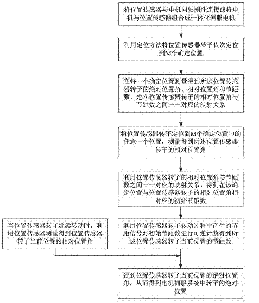
[0077] The present invention can be realized with another kind of method, and its concrete realization steps (1), (3), (4) are identical with above-mentioned invention realization steps, and the realization method of step (2) is as follows:

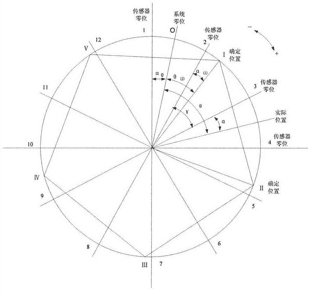
[0078] First, the relative position angle α of any one of the M determined positions is known 1 and pitch number P 1 The one-to-one mapping relationship;

[0079] Then, using the relation: α (i) = α 1 +(β×m-γ×P (i) ), i∈[1,M]

[0080] The one-to-one mapping relationship between the relative position angle and the pitch number of the remaining M-1 determined positions is calculated. in:

[0081] 0≤m≤M, 0≤P (i) ≤N, 0≤α 1 ≤360° / N, 0≤α (i) ≤360° / N;

[0082] N is the number of pole pairs of the position sensor;

[0083] γ is the pitch angle of the position sensor;

[0084] M is the cycle number of the stable position when the motor rotor rotates one revolution;

[0085] β is the periodic angle between two adjacent stable positions...

Embodiment 2

[0088] The present invention can also be realized with a third method, and its concrete realization steps (1), (4) are identical with the implementation steps of the present invention, and the realization method of step (2) is as follows:

[0089] Measure the relative position angle α of any one of the M determined positions 1 and pitch number P 1 The one-to-one mapping relationship;

[0090] The implementation method of step (3) is as follows:

[0091] First, using the same positioning method as step (2), position the position sensor rotor to any one of the M determined positions in step (2), and measure the relative position angle of the position sensor rotor;

[0092] Then, using the relation: α (i) = α 1 +(β×m-γ×P 0 ), i ∈ [1, M]

[0093] Calculate the relative position angle α of the determined position (i) and initial pitch number P 0 One-to-one mapping relationship. in:

[0094] 0≤m≤M, 0≤P 0 ≤N, 0≤α 1 ≤360° / N, 0≤α 0 ≤360° / N;

[0095] N is the number of pol...


PUM


Abstract

The invention discloses a method for measuring the absolute position of a rotor in a motor servo system, comprising the steps of: integrally combining the motor and a position sensor; and by utilizing position information provided by a predetermined position as well as relative position information and pitch information provided by the sensor, and recombining the position information through using a proper method so as to obtain absolute position information of the motor rotor. According to the method, a zero position indicator is not required; after outage, the absolute position of a zero position of a relative system of the motor rotor can be obtained through the predetermined position of the motor rotor; compared with a coarse / fine coupling double-speed rotary transformer system, the high-precision absolute position information is obtained by using the simple and reliable sensor, so that the structure of the integrated high-performance servo motor is simplified and decreased, then the structure is more compact and the volume is decreased; and at the same time, a signal processing circuit and coarse / fine coupling operation are decreased, so that compared with the coarse / fine coupling double-speed rotary transformer system, the performance-price ratio is improved and the complexity level is reduced.

Description

technical field [0001] The invention relates to a method for measuring the absolute position of the rotor in a motor servo system, especially a method for obtaining the absolute position of the motor rotor by using a position sensor similar to the working principle of a multi-pole resolver, which is suitable for servo-driven electromechanical integration products and servo instruments , servo turntable, electric vehicles and other application fields. Background technique [0002] Position sensors are often used in motor servo systems, and resolvers or inductive synchronizers are commonly used position sensors. In an absolute position servo system, the absolute position information is generally obtained through a dual-channel angle measurement system, such as a resolver coarse-fine coupling method; for an absolute position servo system with a limited rotation angle, a multi-pole reluctance resolver or a multi-pole resolver is also used as a The situation of absolute position...

Claims


Application Information

Patent Timeline
Patent Type & Authority Applications(China)
IPC IPC(8): G01B21/00
Inventor 秦和平陈育杰夏刚李庆敏郑宏滨王清正
Owner BEIJING PULIMEN ELECTRO MECHANICAL HIGH TECHN CO
Why Eureka
Try Eureka