ARM and FPGA (Field Programmable Gate Array) architecture based autopilot of fixed wing unmanned aerial vehicle

An autopilot, UAV technology, applied in three-dimensional position/channel control and other directions, can solve the problems of affecting the response speed of the system, large size, low system integration, etc., to reduce additional workload, fast system response, The effect of high work efficiency

Inactive Publication Date: 2012-12-19
BEIJING INSTITUTE OF TECHNOLOGYGY
View PDF4 Cites 51 Cited by
  • Summary
  • Abstract
  • Description
  • Claims
  • Application Information

AI Technical Summary

Problems solved by technology

The disadvantages and shortcomings of these autopilot design schemes are the use of a single processor, which limits the information processing capability. Due to the limited carrying capacity of the drone, most autopilots only use a single processor, which leads to , a single CPU needs to collect and process various sensor data, and also output the peripherals of the UAV for stability and navigation control. The single processor needs to work at full load or even overload, which affects the response speed of the system.
Since the operation of the dual-port RAM itself is relatively complicated, this makes the logic structure of the autopilot system more complicated in terms of software and hardware, additionally increases processor overhead, and makes system debugging difficult.
[0005] Many of the current autopilot devices use finished attitude acquisition devices, so that the autopilot devices contain multiple separate devices, which are large in size and low in system integration. Moreover, the attitude calculation algorithms are not added to the control software of these autopilot devices, which leads to The autopilot cannot fuse and optimize multi-sensor data according to different environmental conditions, which limits the adaptability of the autopilot

Method used


Image

  • ARM and FPGA (Field Programmable Gate Array) architecture based autopilot of fixed wing unmanned aerial vehicle
  • ARM and FPGA (Field Programmable Gate Array) architecture based autopilot of fixed wing unmanned aerial vehicle
  • ARM and FPGA (Field Programmable Gate Array) architecture based autopilot of fixed wing unmanned aerial vehicle

Examples


Embodiment Construction

[0035] The present invention will be described in more detail below in conjunction with the accompanying drawings.

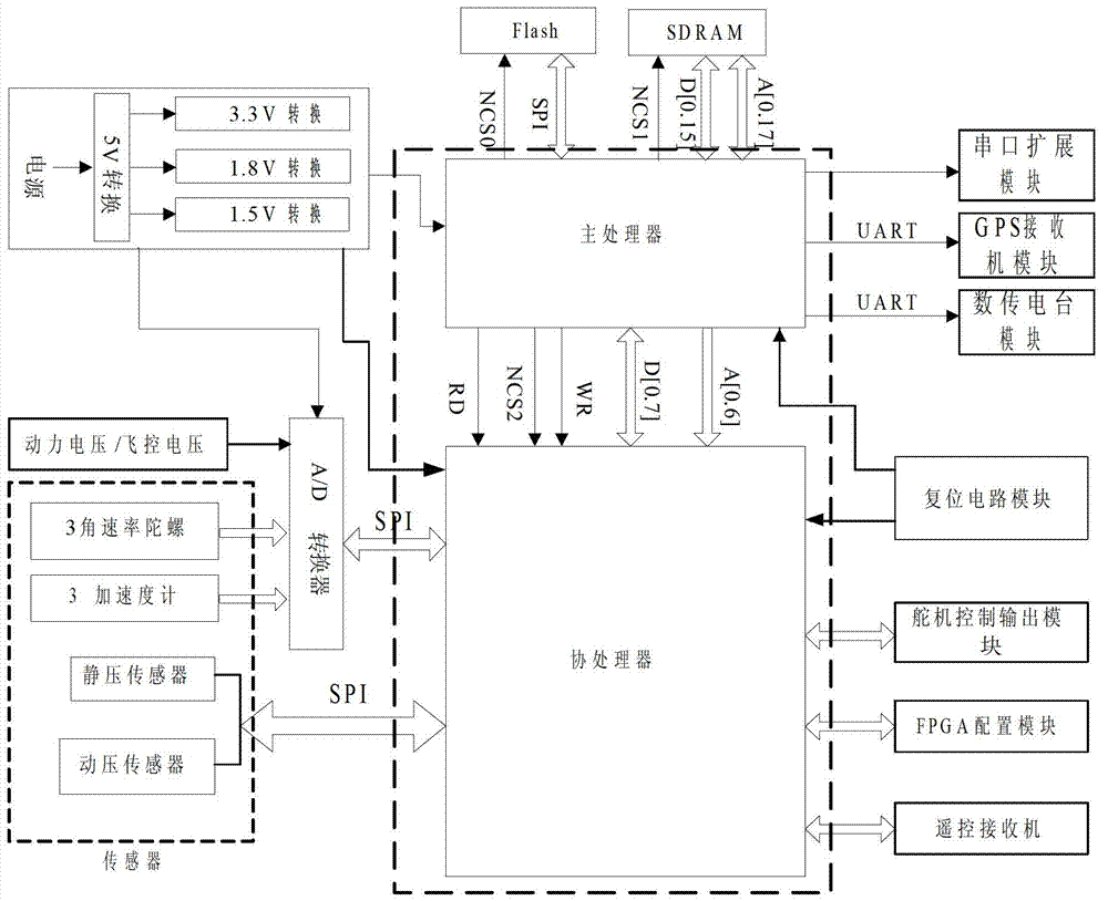
[0036] The block diagram of the present invention is as Figure 1 As shown, including processor module, FLASH module, SDRAM module, FPGA configuration module, sensor module, A / D conversion module, serial port expansion module, servo control signal output module, remote control receiver module, reset circuit module, system power supply module .

[0037] The processor module includes a main processor ARM and a coprocessor FPGA. In the present invention, main processor selects the AT91RM9200 based on ARM9TDMI kernel for use, and it adopts the BGA package of 256 pins, and the performance is up to 200MIPS when working at 180MHz, and the memory management unit has a data cache of 16KB, an instruction cache of 16KB, and its internal SRAM16K, ROM128K , cannot meet the requirements of the present invention, and therefore must be expanded. Coprocessor in the present inv...


PUM


Abstract

The invention relates to an ARM and FPGA (Field Programmable Gate Array) architecture based autopilot of a fixed wing unmanned aerial vehicle, which belongs to the technical field of an embedded-control unmanned aerial vehicle. The autopilot uses two processors. The main processor is responsible for controlling calculation while the slave processor is responsible for collecting and outputting signals. The slave processor is designed as a peripheral device of the main processor. The main processor can operate the slave processor by way of operating the self storage space, so that extra workload due to data exchange between two processors is reduced, work is divided clearly, and the system response speed is fast. A design ideal of a top layer module with multiple bottom layers is adopted with distinct gradations, and operation is carried out by using a state machine in reading of an A/D (Analog/Digital) module, so that the work efficiency is higher.

Description

technical field [0001] The invention relates to an autopilot of a fixed-wing unmanned aerial vehicle based on an ARM and FPGA architecture, and belongs to the technical fields of embedded control and unmanned aerial vehicles. Background technique [0002] The autopilot is an adjustment device that automatically controls the trajectory of the aircraft according to technical requirements. For unmanned aircraft, it can cooperate with other navigation equipment to complete the prescribed flight tasks. Autopilots are widely used in modern aircraft, especially in micro-aircraft or micro-unmanned aerial vehicles. [0003] The existing UAV autopilot generally uses a microprocessor as the CPU to process various input information, and at the same time output the processing results to the peripheral interfaces to drive the peripherals to work, and realize the automatic driving of the UAV. . The processors used by these autopilots are generally single-chip microcomputers, ARM or DSP. ...

Claims


Application Information

Patent Timeline
Patent Type & Authority Applications(China)
IPC IPC(8): G05D1/10
Inventor 耿庆波刘浪华费庆田培岗王晓平
Owner BEIJING INSTITUTE OF TECHNOLOGYGY
Why Eureka
Try Eureka