Over-current protection circuit

An overcurrent protection circuit and circuit technology, applied in emergency protection circuit devices, electrical components, etc., can solve problems such as easy malfunction, large current flowing through resistors, energy loss, etc., to avoid false triggering, avoid malfunction, The effect of improving reliability

Inactive Publication Date: 2012-12-19
UNIV OF ELECTRONICS SCI & TECH OF CHINA
View PDF6 Cites 23 Cited by
  • Summary
  • Abstract
  • Description
  • Claims
  • Application Information

AI Technical Summary

Problems solved by technology

Both of these solutions are easily affected by the peak current when the power tube is turned on, and are prone to malfunction
The former scheme also has the following disadvantages: (1) Due to the discreteness of the process, the resistance value is difficult to be accurate (the error is about 20%); (2) After the source is connected in series with the resistor, the original on-resistance is very large The tube voltage drop of the LDMOS tube further increases, and the power handling capacity becomes weaker; (3) A large current flows through the resistor, causing energy loss and reducing the conversion efficiency of the switching power supply system
In the second scheme, no sampling resistor is needed, and the drain voltage of the LDMOS tube is directly detected, but the application environment is limited

Method used


Image

  • Over-current protection circuit
  • Over-current protection circuit
  • Over-current protection circuit

Examples


Embodiment Construction

[0028] The technical solution of the present invention will be described in detail below in conjunction with the accompanying drawings and embodiments.

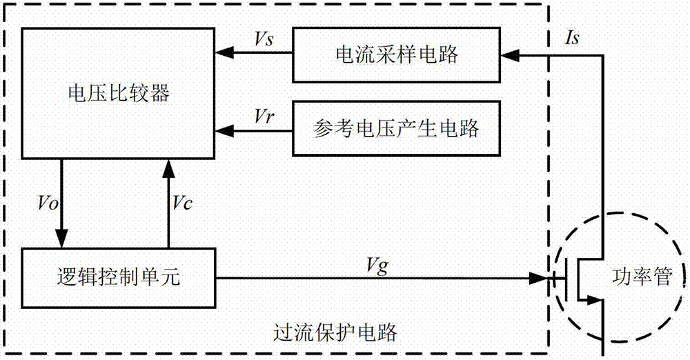
[0029] The structure of the overcurrent protection circuit of the present invention is as follows: figure 1 Shown, including current sampling circuit, reference voltage generation circuit, voltage comparator and logic control unit. figure 1 middle:

[0030] The current sampling circuit is used to sample the current flowing through the power tube, and convert the sampled current Is into a sampled voltage Vs input to the voltage comparator.

[0031] The reference voltage generation circuit is used to generate the reference voltage Vr, which provides a reference voltage for the voltage comparator;

[0032] The voltage comparator is connected to the logic control unit. When the gate control signal Vg output by the logic control unit turns on the power transistor, the sampling voltage Vs is compared with the reference voltage Vr...


PUM


Abstract

The invention relates to the technology of power integrated circuit design and discloses an over-current protection circuit aiming at the shortcoming that an over-current protection circuit is susceptible to power tube peak current interference and unreliable in acquired data in the prior art. The over-current protection circuit mainly comprises a current sampling circuit, a reference voltage generation circuit, a voltage comparator and a logic control unit. Current flowing through a power tube is compared with set reference signals to generate over-current information, and control signals are outputted to control the power tube by means of delay. Since the voltage comparator has delayed processing capacity, influences of peak current can be avoided, reliability of over-current acquired data is improved, and misoperations are avoided. The over-current protection circuit is particularly suitable for integrated circuit products of high-voltage heavy-current power management chips, DC-DC converters and the like.

Description

technical field [0001] The invention relates to power integrated circuit design technology, in particular to a high-voltage integrated overcurrent protection circuit with a wide input range. Background technique [0002] With the rapid development of home appliances and portable electronic devices, power management chips have become a staple product of integrated circuits. This type of chip is internally integrated or needs to be externally connected to a power transistor, which is usually a lateral double-diffused metal oxide semiconductor power transistor, referred to as an LDMOS transistor. In practical applications, LDMOS tubes usually need to be directly connected to high voltage and pass high current, so how to ensure the safe operation of chips and LDMOS tubes is one of the key points of chip design. Especially in the field of medium and high power applications, if the power management chip lacks protection in the event of overcurrent, it is easy to cause damage to t...

Claims


Application Information

Patent Timeline
Patent Type & Authority Applications(China)
IPC IPC(8): H02H7/22
Inventor 罗萍廖乾兰廖鹏飞胡烽甄少伟张波
Owner UNIV OF ELECTRONICS SCI & TECH OF CHINA
Why Eureka
Try Eureka