Large-caliber long-focus collimator focal point real-time monitoring system

A technology of real-time monitoring system and collimator light pipe, which is used in optical instrument testing, optics, measuring devices, etc., can solve the problem of not mentioning environmental parameters. And perfect, can not fully simulate the complexity of the real environment and other problems, to achieve the effect of light weight, meet the accuracy requirements, save the complex process

Inactive Publication Date: 2012-12-26
CHANGCHUN INST OF OPTICS FINE MECHANICS & PHYSICS CHINESE ACAD OF SCI
View PDF4 Cites 11 Cited by
  • Summary
  • Abstract
  • Description
  • Claims
  • Application Information

AI Technical Summary

Problems solved by technology

Although this method is simple, it cannot fully simulate the complexity of the real environment, and the accuracy is not enough.
[0006] 3) Image processing method: by evaluating and processing the blurred image formed by the system when the system is out of focus, the defocus amount of the system at that time is calculated. Although this method has high real-time performance and good accuracy, it is only suitable for transmission-type spaces Imaging systems such as cameras or microscopes
The system’s emitting light path and receiving light path are not in the same plane, the system light source and the CCD as a photoelectric conversion device will occupy two positions of the focal plane of the space camera at the same

Method used


Image

  • Large-caliber long-focus collimator focal point real-time monitoring system
  • Large-caliber long-focus collimator focal point real-time monitoring system
  • Large-caliber long-focus collimator focal point real-time monitoring system

Examples


Embodiment Construction

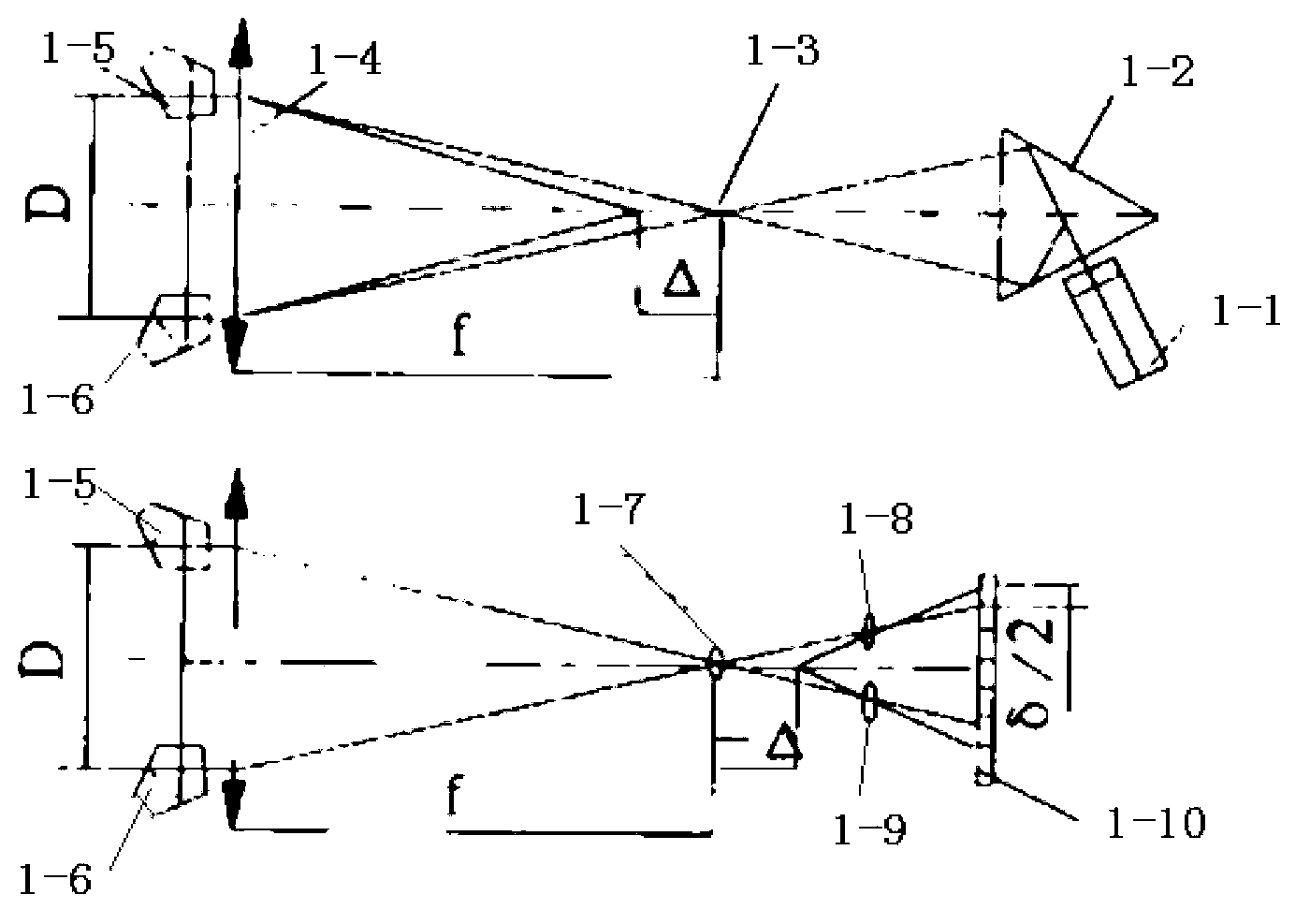
[0031] Such as figure 1As shown, the focus detection system of the prior art focus monitoring device includes a laser 1-1, a beam splitting prism 1-2, a slit 1-3, two pentaprisms 1-5, 1-6, and two separation lenses 1-8 , 1-9, consisting of a processor (not shown in the figure). The light emitted by the laser 1-1 becomes collimated light after passing through the main mirror of the camera. Using the right-angle reflection characteristics of the two pentaprisms, the target slit image 1-3 is reflected, and then imaged on the focal plane through the main mirror. At the field lens 1-7; two separation lenses 1-8 and 1-9 are arranged behind the field lens 1-7, and the target slit image 1-3 is imaged on the camera CCD receiver 1-10 respectively. When the camera is out of focus, the distance between the two slit images imaged on the CCD receiver 1-10 changes, and the processor can calculate the direction and size of the defocus according to the direction and size of the change.

[00...


PUM


Abstract

The invention relates to a large-caliber long-focus collimator focal point real-time monitoring system. A laser device of the system emits laser beams, and the laser beams are divided into two bunches of lasers through a laser beam splitter. The two bunches of lasers pass through a slit after being reflected by a semi-reflecting and semi-transparent lens, and then are reflected to a main lens of the collimator through a reflecting lens. The two bunches lasers reflected by the main lens are reflected four times in turnover mode by two pentaprisms, and then are reflected back through the main lens. The two bunches lasers pass through the slit again after being reflected by the reflecting lens, and pass through two sets of dialyte lenses behind the semi-reflecting and semi-transparent lens and are converged on a charge coupled device (CCD). A processor calculates the distance between two faculaes according to image data received by the CCD, and then size and direction of defocusing amount can be obtained. An emitting light path and a receiving light path are in the same plane, and relative positions of elements are easy to guarantee when the large-caliber long-focus collimator focal point real-time monitoring system is mounted so as to reduce mounting and adjusting difficulty of the whole system.

Description

technical field [0001] The invention relates to a real-time monitoring system for the focal point of a collimated light tube with a large diameter and a long focal length. Background technique [0002] As humans continue to explore the depths of space, space optics has been greatly developed. Various large-scale space telescopes and space cameras emerge in endlessly, and their apertures are also getting larger and larger, such as: the Hubble telescope with an aperture of 2.4 m, and a single aperture of 8.4 m. m LBT telescope, 6.5 m James space-based telescope, and 25 m GMT ground-based telescope. Therefore, the large-aperture detection system is more and more widely used in the scientific research work of calibration and detection, and its core equipment is a large-aperture collimator. However, as the aperture of the collimator becomes larger and the focal length becomes longer, the process of adjusting and calibrating the collimator becomes very cumbersome, and its image q...

Claims


Application Information

Patent Timeline
IPC IPC(8): G01M11/00G02B17/08
Inventor 李响张晓辉
Owner CHANGCHUN INST OF OPTICS FINE MECHANICS & PHYSICS CHINESE ACAD OF SCI
Why Eureka
Try Eureka